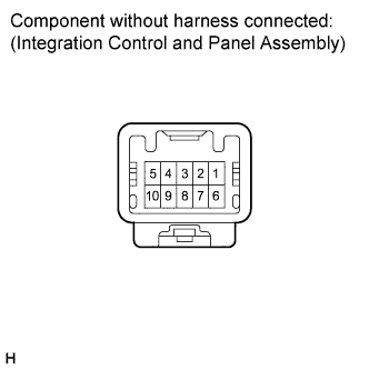
 |
Measure the resistance according to the value(s) in the table below.
- Standard resistance:
Tester Connection Switch Condition Specified Condition 4 - 5 ON Below 1 Ω OFF 10 kΩ or higher
HAZARD WARNING SWITCH > INSPECTION |
| 1. INSPECT INTEGRATION CONTROL AND PANEL ASSEMBLY (w/o Navigation System) |
|
Measure the resistance according to the value(s) in the table below.
| Tester Connection | Switch Condition | Specified Condition |
| 4 - 5 | ON | Below 1 Ω |
| OFF | 10 kΩ or higher |
Connect the (+) lead from the battery to terminal 6 and the (-) lead to terminal 7.
Check that the illumination of the switch comes on.
| 2. INSPECT NAVIGATION RECEIVER ASSEMBLY (w/ Navigation System) |
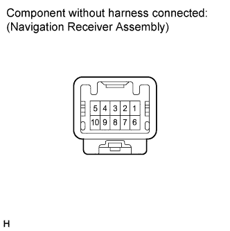 |
Measure the resistance according to the value(s) in the table below.
| Tester Connection | Switch Condition | Specified Condition |
| 4 - 5 | ON | Below 1 Ω |
| OFF | 10 kΩ or higher |
Connect the (+) lead from the battery to terminal 6 and the (-) lead to terminal 7.
Check that the illumination of the switch comes on.