FRONT COOLING UNIT > REASSEMBLY |
| 1. INSTALL NO. 1 COOLER THERMISTOR |
![]() |
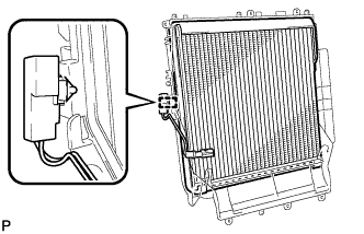
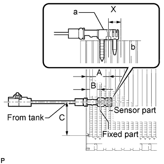
Install the No. 1 cooler thermistor as shown in the illustration.
| Part | Length | |
| A | 34.3 mm | 1.35 in. |
| B | 20.9 mm | 0.82 in. |
| C | 50 mm | 1.96 in. |
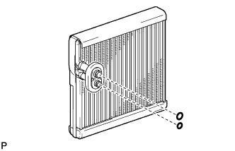
| 2. INSTALL NO. 1 COOLER EVAPORATOR SUB-ASSEMBLY |
![]() |
Sufficiently apply compressor oil to 2 new O-rings and the fitting surfaces.
Install the 2 O-rings to the No. 1 cooler evaporator sub-assembly.
![]() |
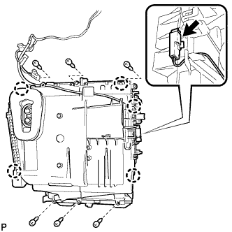
Install the No. 1 cooler evaporator sub-assembly.
Engage the clamp.
![]() |
Engage the 5 claws.
Install the plate cover with the 6 screws.
Connect the connector.
| 3. INSTALL COOLER EXPANSION VALVE |
![]() |
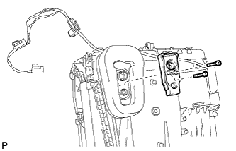
Using a 4 mm hexagon wrench, install the cooler expansion valve with the 2 hexagon bolts.
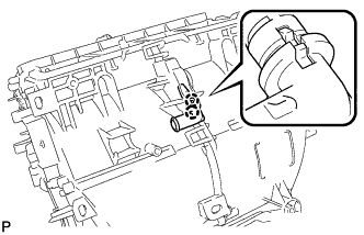
| 4. INSTALL ASPIRATOR (for Manual Air Conditioning System) |
![]() |
Engage the 2 claws and install the aspirator.
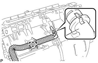
| 5. INSTALL ASPIRATOR (for Automatic Air Conditioning System) |
![]() |
Engage the 2 claws.
Engage the clamp and install the aspirator.
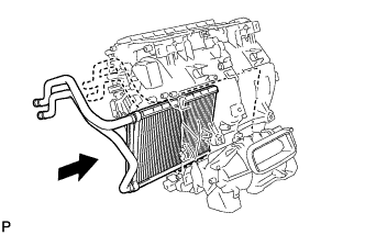
| 6. INSTALL HEATER RADIATOR UNIT SUB-ASSEMBLY |
![]() |
Install the heater radiator unit sub-assembly as shown in the illustration.
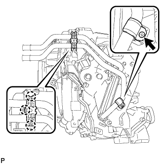
| 7. INSTALL HEATER CLAMP |
![]() |
Install the clamp with the screw.
Engage the 3 claws and install the heater clamp.
| 8. INSTALL FRONT AIR MIX CONTROL SERVO MOTOR SUB-ASSEMBLY |
![]() |
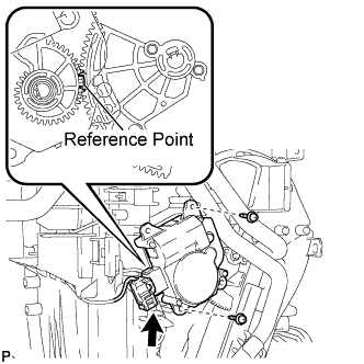
Using the reference point, install the front air mix control servo motor sub-assembly with the 2 screws.
Connect the connector.
| 9. INSTALL FRONT AIR OUTLET CONTROL SERVO MOTOR SUB-ASSEMBLY |
![]() |
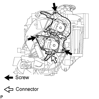
Install the front air outlet control servo motor sub-assembly with the 3 screws.
Connect the 2 connectors.
| 10. INSTALL BLOWER ASSEMBLY |
![]() |
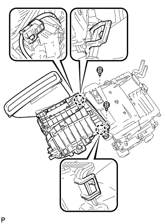
Engage the 2 claws.
Install the blower assembly with the 2 screws.
Connect the connector.
| 11. INSTALL QUICK HEATER ASSEMBLY (w/ PTC Heater) |
![]() |
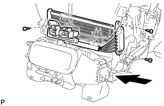
Install the quick heater assembly as shown in the illustration.
Install the 3 screws.
| 12. INSTALL NO. 3 AIR DUCT SUB-ASSEMBLY |
![]() |
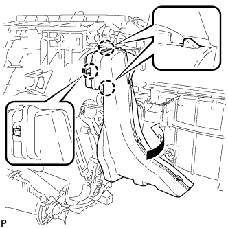
Engage the 3 claws and install the No. 3 air duct sub-assembly as shown in the illustration.
| 13. INSTALL TRANSPONDER KEY ECU (w/o Smart Key System) |
![]() |
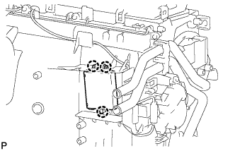
Engage the 3 claws and install the transponder key ECU as shown in the illustration.
| 14. INSTALL ID CODE BOX (IMMOBILISER CODE ECU) (w/ Smart Key System) |
![]() |
Engage the 3 claws and install the ID code box (immobiliser code ECU) as shown in the illustration.