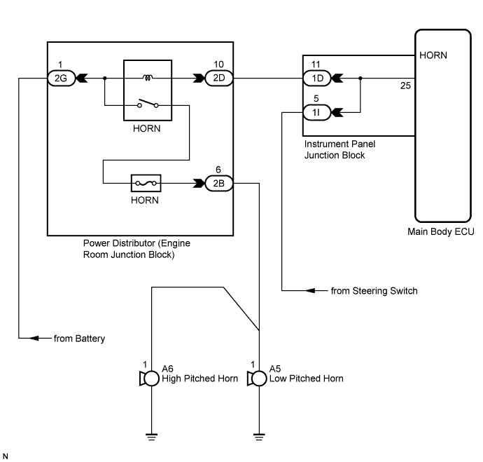
THEFT DETERRENT SYSTEM (w/o Smart Key System) > Horn Circuit |
| 1.INSPECT HORNS |
Press the horn switch and check if the horns sound.
| Result | Proceed to |
| Horns sound | A |
| Horns do not sound | B |
|
| ||||
| A | |
 |
| 2.PERFORM ACTIVE TEST USING TECHSTREAM |
Connect Techstream to the DLC3.
Turn the ignition switch to the ON position.
Turn Techstream main switch on.
Select the item below in the Active Test and then check that the horns operate.
| Tester Display | Test Part | Control Range | Diagnostic Note |
| Vehicle Horn | Vehicle horns | ON / OFF | - |
|
| ||||
| OK | ||
 | ||
| ||
| 3.CHECK HARNESS AND CONNECTOR (INSTRUMENT PANEL JUNCTION BLOCK - ENGINE ROOM JUNCTION BLOCK) |
Disconnect the ID instrument panel junction block connector and 2D engine room junction block connector.
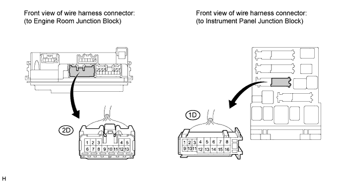
Measure the resistance according to the value(s) in the table below.
| Tester Connection | Condition | Specified Condition |
| 1D-11 - 2D-10 | Always | Below 1 Ω |
| 1D-11 - Body ground | Always | 10 kΩ or higher |
|
| ||||
| OK | ||
| ||
| ||

