 |
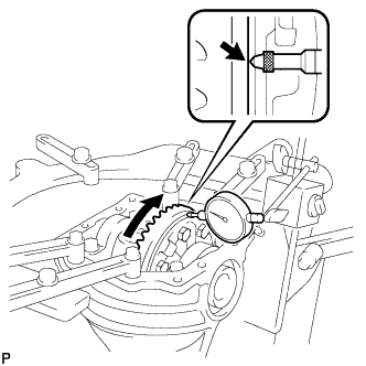
Using a dial indicator, check the runout of the differential ring gear.
- Maximum runout:
- 0.07 mm (0.0028 in.)
REAR DIFFERENTIAL CARRIER ASSEMBLY > INSPECTION |
| 1. INSPECT RUNOUT OF DIFFERENTIAL RING GEAR |
|
Using a dial indicator, check the runout of the differential ring gear.
| 2. INSPECT DIFFERENTIAL RING GEAR BACKLASH |
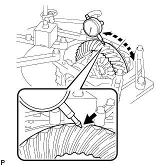 |
Using a dial indicator, check the backlash of the differential ring gear.
| 3. INSPECT DIFFERENTIAL PINION AND SIDE GEAR |
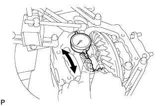 |
Using a dial indicator, check the backlash of the differential side gear while holding one of the pinion gears toward the differential case assembly.
| 4. INSPECT RUNOUT OF REAR DRIVE PINION COMPANION FLANGE SUB-ASSEMBLY |
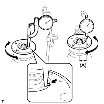 |
Using a dial indicator, measure the runout of the rear drive pinion companion flange sub-assembly vertically and horizontally.
| 5. INSPECT DIFFERENTIAL DRIVE PINION PRELOAD |
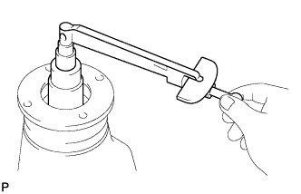 |
Using a torque wrench, measure the preload of the differential drive pinion.
| Item | Preload |
| New bearing | 1.1 to 1.7 N*m (11.2 to 17.3 kgf*cm, 9.7 to 15.0 in.*lbf) |
| Reused bearing | 0.6 to 0.9 N*m (6.1 to 9.2 kgf*cm, 5.3 to 8.0 in.*lbf) |
| 6. INSPECT TOTAL PRELOAD |
|
Using a torque wrench, measure the total preload.
| 7. INSPECT DIFFERENTIAL CASE ASSEMBLY |
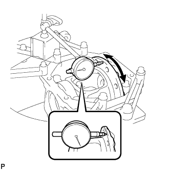 |
Install the rear differential case to the rear differential carrier sub-assembly.
Install the right and left rear differential bearing caps with the 4 bolts.
Using a dial indicator, measure the differential case runout.
Remove the rear differential case.
| 8. INSPECT DIFFERENTIAL RING GEAR |
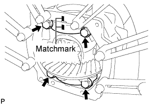 |
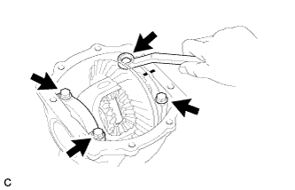
Install the rear differential case to the rear differential carrier sub-assembly, and install the 2 rear differential side gear shaft plate washers so that there is no play in the bearing.
Align the matchmarks on the bearing cap and differential carrier, and install the 2 bearing caps.
Tighten both rear differential bearing caps with the 4 bolts.
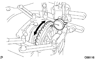 |
Using a dial indicator, measure the runout of the differential ring gear.
 |
Remove the 2 rear differential bearing caps, 2 rear differential side gear shaft plate washers and differential case assembly.
| 9. INSPECT TOOTH CONTACT BETWEEN RING GEAR AND DRIVE PINION |
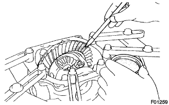 |
Coat 3 or 4 teeth at 3 different positions on the differential ring gear with Prussian blue.
Hold the rear drive pinion companion flange sub-assembly firmly and rotate the differential ring gear in both directions.
Inspect the tooth contact pattern.
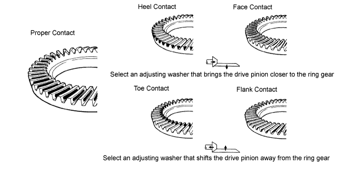
| Thickness mm (in.) | Thickness mm (in.) | Thickness mm (in.) |
| 2.26 to 2.28 (0.0890 to 0.0898) | 2.41 to 2.43 (0.0949 to 0.0957) | 2.56 to 2.58 (0.1008 to 0.1016) |
| 2.29 to 2.31 (0.0902 to 0.0909) | 2.44 to 2.46 (0.0961 to 0.0969) | 2.59 to 2.61 (0.1020 to 0.1028) |
| 2.32 to 2.34 (0.0913 to 0.0921) | 2.47 to 2.49 (0.0972 to 0.0980) | 2.62 to 2.64 (0.1031 to 0.1039) |
| 2.35 to 2.37 (0.0925 to 0.0933) | 2.50 to 2.52 (0.0984 to 0.0992) | 2.65 to 2.67 (0.1043 to 0.1051) |
| 2.38 to 2.40 (0.0937 to 0.0945) | 2.53 to 2.55 (0.0996 to 0.1004) | 2.68 to 2.70 (0.1055 to 0.1063) |