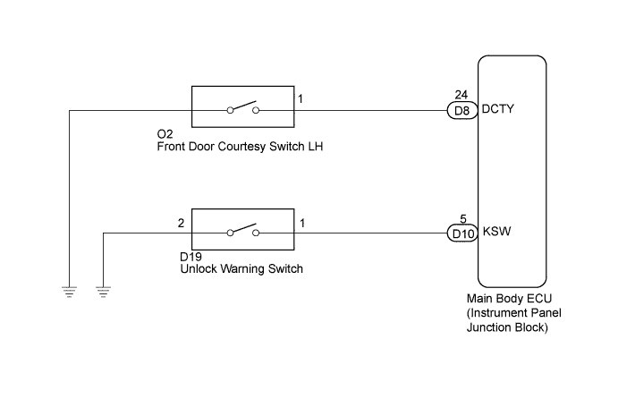
POWER DOOR LOCK CONTROL SYSTEM > Key Lock-in Prevention Function does not Work Properly |
| 1.READ VALUE USING TECHSTREAM (UNLOCK WARNING SWITCH) |
Connect Techstream to the DLC3.
Turn the ignition switch on (IG).
Turn the tester on.
Enter the following menus:
Body Electrical / Main Body / Data List.
Select Key Unlock Warning SW in the Data List and read the tester display.
| Tester Display | Measurement Item/Range | Normal Condition | Diagnostic Note |
| Key Unlock Warning SW | Unlock warning switch signal/ON or OFF | ON: Key is in ignition key cylinder OFF: No key is in ignition key cylinder | - |
|
| ||||
| OK | |
 |
| 2.READ VALUE USING TECHSTREAM (DRIVER SIDE DOOR COURTESY LIGHT SWITCH) |
Connect Techstream to the DLC3.
Turn the ignition switch on (IG).
Turn the tester on.
Enter the following menus:
Body Electrical / Main Body / Data List.
Select D Door Courtesy SW in the Data List and read the tester display.
| Tester Display | Measurement Item/Range | Normal Condition | Diagnostic Note |
| D Door Courtesy SW | Driver side door courtesy light switch signal/ON or OFF | ON: Driver side door is open OFF: Driver side door is closed | - |
|
| ||||
| OK | ||
 | ||
| ||
| 3.INSPECT FRONT DOOR COURTESY LIGHT SWITCH ASSEMBLY |
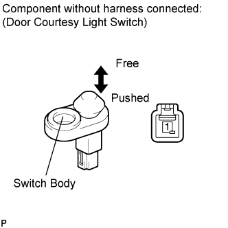 |
Remove the driver side door courtesy light switch (Click here).
Measure the resistance according to the value(s) in the table below.
| Tester Connection | Condition | Specified Condition |
| 1 - Switch ground | Not pushed (ON) | Below 1 Ω |
| 1 - Switch ground | Pushed (OFF) | 10 kΩ or higher |
|
| ||||
| OK | |
|
| 4.CHECK HARNESS AND CONNECTOR (FRONT DOOR COURTESY SWITCH CIRCUIT) |
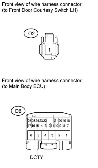 |
Disconnect the main body ECU (instrument panel junction block) connector.
Measure the resistance according to the value(s) in the table below.
| Tester Connection | Condition | Specified Condition |
| O2-1 - D8-24 (DCTY) | Always | Below 1 Ω |
| O2-1 - Body ground | Always | 10 kΩ or higher |
|
| ||||
| OK | ||
| ||
| ||
| 5.INSPECT UNLOCK WARNING SWITCH ASSEMBLY |
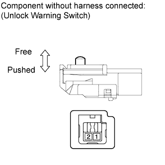 |
Remove the unlock warning switch (Click here).
Measure the resistance according to the value(s) in the table below.
| Tester Connection | Switch Condition | Specified Condition |
| 1 - 2 | Pushed | Below 1 Ω |
| 1 - 2 | Not pushed | 10 kΩ or higher |
|
| ||||
| OK | |
|
| 6.CHECK HARNESS AND CONNECTOR (UNLOCK WARNING SWITCH CIRCUIT) |
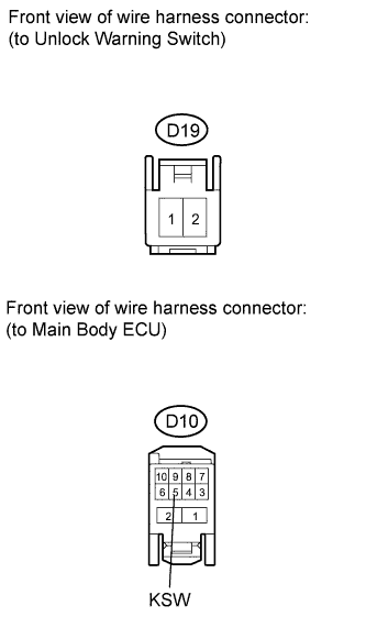 |
Disconnect the main body ECU (instrument panel junction block) connector.
Measure the resistance according to the value(s) in the table below.
| Tester Connection | Condition | Specified Condition |
| D19-1 - D10-5 (KSW) | Always | Below 1 Ω |
| D19-1 - Body ground | Always | 10 kΩ or higher |
| D19-2 - Body ground | Always | Below 1 Ω |
|
| ||||
| OK | ||
| ||
| ||

