 |
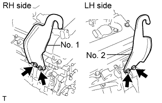
Remove the engine hangers.
ENGINE UNIT > REMOVAL |
| 1. INSTALL ENGINE STAND |
Secure the engine onto an engine stand with the bolts.
|
Remove the engine hangers.
| 2. REMOVE IGNITION COIL ASSEMBLY |
Remove the 6 bolts and 6 ignition coils.
| 3. REMOVE NO. 2 ENGINE MOUNTING STAY RH |
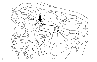 |
Remove the bolt and No. 2 engine mounting stay RH.
| 4. REMOVE INTAKE MANIFOLD |
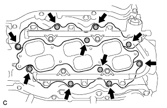 |
Uniformly loosen and remove the 6 bolts and 4 nuts.
Remove the intake manifold and 2 gaskets.
| 5. REMOVE EXHAUST MANIFOLD SUB-ASSEMBLY RH |
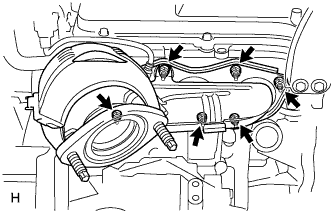 |
Uniformly loosen and remove the 6 nuts.
Remove the exhaust manifold sub-assembly and gasket.
| 6. REMOVE NO. 2 ENGINE OIL LEVEL DIPSTICK GUIDE |
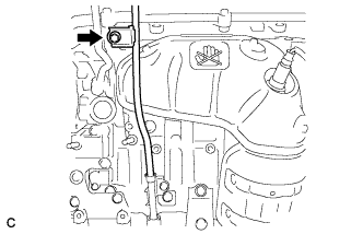 |
Remove the oil level dipstick.
Remove the bolt and No. 2 engine oil level dipstick guide.
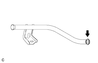 |
Remove the O-rings from the No. 2 engine oil level dipstick guide.
| 7. REMOVE NO. 2 MANIFOLD STAY |
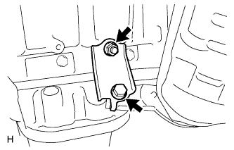 |
Remove the bolt, nut and No. 2 manifold stay.
| 8. REMOVE NO. 2 EXHAUST MANIFOLD HEAT INSULATOR |
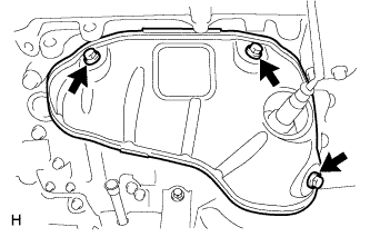 |
Remove the 3 bolts and No. 2 exhaust manifold heat insulator.
| 9. REMOVE EXHAUST MANIFOLD SUB-ASSEMBLY LH |
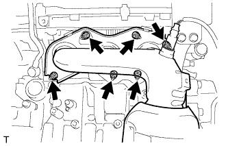 |
Uniformly loosen and remove the 6 nuts.
Remove the exhaust manifold assembly and gasket.
| 10. REMOVE TRANSVERSE ENGINE MOUNTING BRACKET |
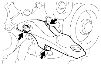 |
Remove the 3 bolts and transverse engine mounting bracket.
| 11. REMOVE TRANSVERSE ENGINE MOUNTING BRACKET (for 2WD) |
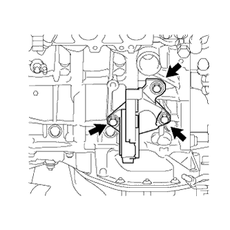 |
Remove the 3 bolts and transverse engine mounting bracket.
| 12. REMOVE TRANSVERSE ENGINE MOUNTING BRACKET (for 4WD) |
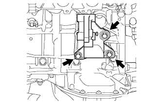 |
Remove the 3 bolts and transverse engine mounting bracket.
| 13. REMOVE GENERATOR ASSEMBLY |
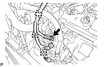 |
Remove the terminal cap.
Remove the nut and disconnect the wire harness from terminal B.
Disconnect the generator connector from the generator assembly.
Disconnect the connector from the compressor and magnetic clutch.
Disconnect the 3 wire harness clamps.
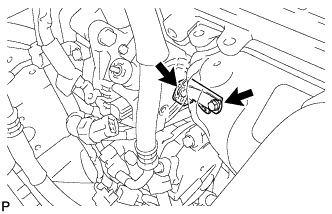 |
Remove the 2 bolts, and then disconnect the bracket.
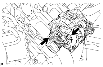 |
Remove the 2 bolts and the generator assembly.
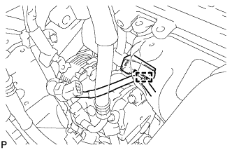 |
Disconnect the wire harness clamp, and then remove the generator bracket.
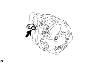 |
Remove the bolt and the wire harness clamp stay.
| 14. REMOVE V-RIBBED BELT TENSIONER ASSEMBLY |
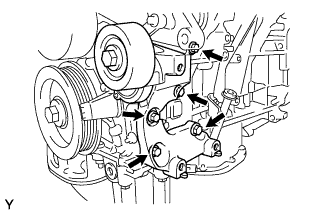 |
Remove the 5 bolts and V-ribbed belt tensioner assembly.
| 15. REMOVE NO. 2 TIMING GEAR COVER |
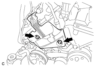 |
Remove the 2 bolts and No. 2 timing gear cover.
| 16. REMOVE NO. 2 IDLER PULLEY SUB-ASSEMBLY |
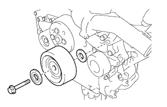 |
Remove the bolt, No. 2 idler pulley cover plate, No. 2 idler pulley sub-assembly and idler pulley cover plate.
| 17. REMOVE WATER PUMP PULLEY |
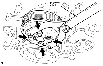 |
Using SST, hold the water pump pulley.
Remove the 4 bolts and water pump pulley.
| 18. REMOVE RADIO SETTING CONDENSER |
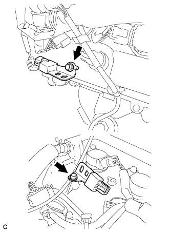 |
Remove the 2 bolts and 2 radio setting condensers.
| 19. REMOVE NO. 1 VACUUM SWITCHING VALVE |
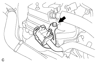 |
Remove the bolt and No. 1 vacuum switching valve.
| 20. REMOVE ENGINE OIL PRESSURE SWITCH ASSEMBLY |
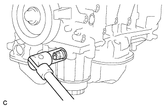 |
Using a 24 mm deep socket wrench, remove the engine oil pressure switch assembly.
| 21. REMOVE KNOCK CONTROL SENSOR WIRE |
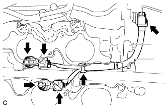 |
Disconnect the 2 knock control sensor connectors and 3 clamps, and remove the knock control sensor wire from the engine assembly.
| 22. REMOVE KNOCK CONTROL SENSOR |
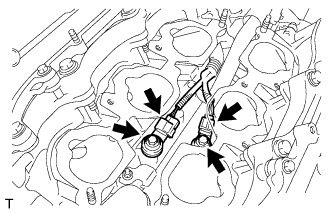 |
Disconnect the 2 knock control sensor connectors.
Remove the 2 bolts and then remove the 2 knock control sensors.
| 23. REMOVE ENGINE COOLANT TEMPERATURE SENSOR |
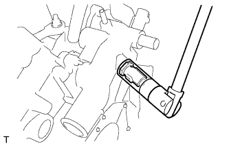 |
Using a 19 mm deep socket wrench, remove the engine coolant temperature sensor and gasket.