 |
Disconnect the exhaust camshaft VVT sensor connector.
DTC P0365 Camshaft Position Sensor "B" Circuit (Bank 1) |
DTC P0367 Camshaft Position Sensor "B" Circuit Low Input (Bank 1) |
DTC P0368 Camshaft Position Sensor "B" Circuit High Input (Bank 1) |
DTC P0390 Camshaft Position Sensor "B" Circuit (Bank 2) |
DTC P0392 Camshaft Position Sensor "B" Circuit Low Input (Bank 2) |
DTC P0393 Camshaft Position Sensor "B" Circuit High Input (Bank 2) |
| DTC No. | DTC Detection Condition | Trouble Area |
| P0365 P0390 |
|
|
| P0367 P0392 | Output voltage of VVT sensor is 0.3 V or less for 4 seconds (1 trip detection logic) |
|
| P0368 P0393 | Output voltage of VVT sensor is 4.7 V or more for 4 seconds (1 trip detection logic) |
|
| Related DTCs | P0365: Exhaust VVT Position (Bank 1) range check / rationality P0365: Exhaust VVT Position (Bank 1) range check (chattering) P0367: Exhaust VVT Position (Bank 1) range check (low voltage) P0368: Exhaust VVT Position (Bank 1) range check (high voltage) P0390: Exhaust VVT Position (Bank 2) range check / rationality P0390: Exhaust VVT Position (Bank 2) range check (chattering) P0392: Exhaust VVT Position (Bank 2) range check (low voltage) P0393: Exhaust VVT Position (Bank 2) range check (high voltage) |
| Required Sensors / Components (Main) | Exhaust VVT Position (Bank 1 and 2) |
| Required Sensors / Components (Related) | Exhaust camshaft sensor |
| Frequency of Operation | Continuous |
| Duration | 5 seconds: Exhaust VVT Position range check / rationality 4 seconds: Others |
| MIL Operation | Immediate: Others |
| Sequence of Operation | None |
| The monitor will run whenever these DTCs are not present | None |
| Engine RPM | 600 rpm or more |
| Starter | OFF |
| Battery voltage | 8 V or more |
| Ignition Switch | on (IG) |
| Starter | OFF |
| Ignition switch on (IG) and time after ignition switch is off to on | 2 seconds or more |
| Battery voltage | 8 V or more |
| Exhaust camshaft sensor signal | No signal |
| Exhaust camshaft sensor signal | Less than 0.3 V, or more than 4.7 V |
| Exhaust camshaft sensor signal | Less than 0.3 V |
| Exhaust camshaft sensor signal | More than 4.7 V |
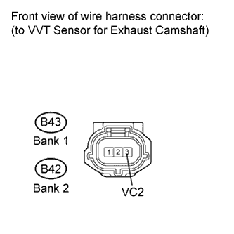
| 1.CHECK VVT SENSOR FOR EXHAUST CAMSHAFT (SENSOR POWER SOURCE) |
|
Disconnect the exhaust camshaft VVT sensor connector.
Turn the ignition switch on (IG).
Measure the voltage according to the value(s) in the table below.
| Tester Connection | Switch Condition | Specified Condition |
| B43-3 (VC2) - Body ground | Ignition switch on (IG) | 4.5 to 5.0 V |
| Tester Connection | Switch Condition | Specified Condition |
| B42-3 (VC2) - Body ground | Ignition switch on (IG) | 4.5 to 5.0 V |
Reconnect the VVT sensor connector.
|
| ||||
| OK | |
 |
| 2.CHECK HARNESS AND CONNECTOR (VVT SENSOR - ECM) |
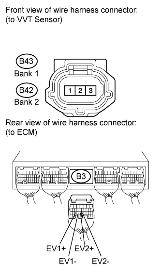 |
Disconnect the exhaust camshaft VVT sensor connector.
Disconnect the ECM connector.
Measure the resistance between the wire harness side connectors.
| Tester Connection | Condition | Specified Condition |
| B43-1 (EX+) - B3-25 (EV1+) | Always | Below 1 Ω |
| B43-2 (EX-) - B3-24 (EV1-) | Always | Below 1 Ω |
| Tester Connection | Condition | Specified Condition |
| B42-1 (EX+) - B3-23 (EV2+) | Always | Below 1 Ω |
| B42-2 (EX-) - B3-22 (EV2-) | Always | Below 1 Ω |
| Tester Connection | Condition | Specified Condition |
| B43-1 (EX+) - B3-25 (EV1+) - Body ground | Always | 10 kΩ or higher |
| B43-2 (EX-) - B3-24 (EV1-) - Body ground | Always | 10 kΩ or higher |
| Tester Connection | Condition | Specified Condition |
| B42-1 (EX+) - B3-23 (EV2+) - Body ground | Always | 10 kΩ or higher |
| B42-2 (EX-) - B3-22 (EV2-) - Body ground | Always | 10 kΩ or higher |
Reconnect the VVT sensor connector.
Reconnect the ECM connector.
|
| ||||
| OK | |
|
| 3.CHECK VVT SENSOR FOR EXHAUST CAMSHAFT (SENSOR INSTALLATION) |
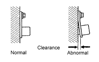 |
Check the VVT sensor installation.
|
| ||||
| OK | |
|
| 4.CHECK EXHAUST CAMSHAFT |
Check the teeth of the camshaft.
|
| ||||
| OK | |
|
| 5.REPLACE VVT SENSOR (FOR EXHAUST CAMSHAFT) |
Replace the VVT sensor (Click here).
| NEXT | |
|
| 6.CHECK WHETHER DTC OUTPUT RECURS |
Connect the Techstream to the DLC3.
Turn the ignition switch on (IG).
Turn the tester on.
Clear the DTCs.
Select the following menu items: Powertrain / Engine and ECT / Trouble Code / Pending.
Read the DTCs.
| Display (DTC Output) | Proceed to |
| No output | A |
| P0365, P0352, P0353, P0354, P0355 or P0356 | B |
|
| ||||
| A | ||
 | ||
| ||
| 7.CHECK HARNESS AND CONNECTOR (VVT SENSOR - ECM) |
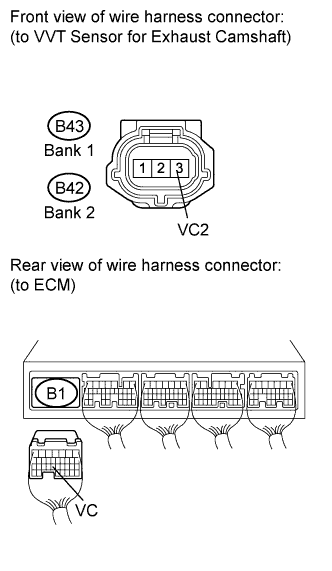 |
Disconnect the exhaust camshaft VVT sensor connector.
Disconnect the ECM connector.
Measure the resistance according to the value(s) in the table below.
| Tester Connection | Condition | Specified Condition |
| B43-3 (VC2) - B1-23 (VC) | Always | Below 1 Ω |
| Tester Connection | Condition | Specified Condition |
| B42-3 (VC2) - B1-23 (VC) | Always | Below 1 Ω |
| Tester Connection | Condition | Specified Condition |
| B43-3 (VC2) or B1-23 (VC) - Body ground | Always | 10 kΩ or higher |
| Tester Connection | Condition | Specified Condition |
| B42-3 (VC2) or B1-23 (VC) - Body ground | Always | 10 kΩ or higher |
Reconnect the VVT sensor connector.
Reconnect the ECM connector.
|
| ||||
| OK | ||
| ||
| ||

