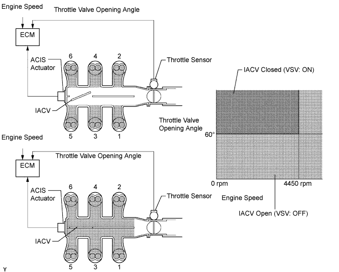
SFI SYSTEM > ACIS Control Circuit |
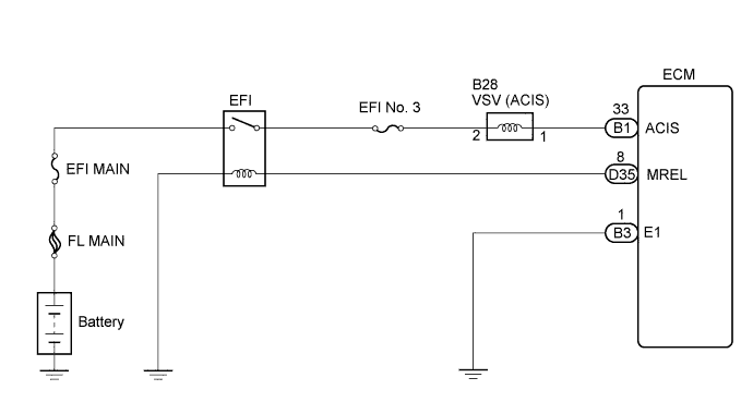
| 1.PERFORM ACTIVE TEST USING TECHSTREAM (ACTIVE THE VSV FOR INTAKE CONTROL) |
Connect the Techstream to the DLC3.
Start the engine and turn the tester on.
Select the following menu items: Powertrain / Engine and ECT / Active Test / Active the VSV for Intake Control.
Check the operation of the VSV when the intake air control is operated by the tester.
|
| ||||
| OK | ||
 | ||
| ||
| 2.CHECK INTAKE AIR CONTROL VALVE (OPERATION) |
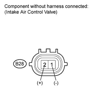 |
Disconnect the intake air control valve connector.
Apply battery voltage between the terminals of the air intake valve connector.
Check the air intake valve operation.
Reconnect the intake air control valve connector.
|
| ||||
| OK | |
 |
| 3.INSPECT TERMINAL VOLTAGE (INTAKE AIR CONTROL VALVE CONNECTOR) |
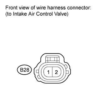 |
Disconnect the intake air control valve connection.
Turn the ignition switch on (IG).
Measure the voltage according to the value(s) in the table below.
| Tester Connection | Switch Condition | Specified Condition |
| 2 - Body ground | Ignition switch on (IG) | 9 to 14 V |
Reconnect the intake air control valve connector.
|
| ||||
| OK | |
|
| 4.CHECK HARNESS AND CONNECTOR (INTAKE AIR CONTROL VALVE - ECM) |
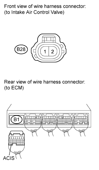 |
Disconnect the intake air control valve connector.
Disconnect the ECM connector.
Measure the resistance according to the value(s) in the table below.
| Tester Connection | Condition | Specified Condition |
| B28-1 - B1-33 (ACIS) | Always | Below 1 Ω |
| Tester Connection | Condition | Specified Condition |
| B28-1 or B1-33 (ACIS) - Body ground | Always | 10 kΩ or higher |
Reconnect the intake air control valve connector.
Reconnect the ECM connector.
|
| ||||
| OK | ||
| ||
| ||

