Home › BODY ELECTRICAL › WIPER AND WASHER › WIPER SWITCH

WIPER SWITCH > INSPECTION

for Preparation Click here


1. INSPECT WINDSHIELD WIPER SWITCH ASSEMBLY


    E144464E12
  1. Check the front wiper switch.

    1. Measure the resistance according to the value(s) in the table below.

      Standard resistance:
      Tester Connection
      Switch Condition
      Specified Condition
      D17-1 (+S) - D17-3 (+1)
      INT
      Below 1 Ω
      OFF
      D17-2 (+B) - D17-3 (+1)
      MIST
      LO
      D17-2 (+B) - D17-4 (+2)
      HI

      If the result is not as specified, replace the switch assembly.
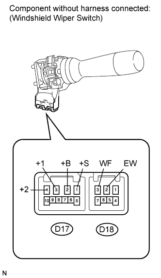
  1. Check the front washer switch.

    1. Measure the resistance according to the value(s) in the table below.

      Standard resistance:
      Tester Connection
      Switch Condition
      Specified Condition
      D18-2 (EW) - D18-3 (WF)
      ON
      Below 1 Ω
      OFF
      10 kΩ or higher

      If the result is not as specified, replace the switch assembly.
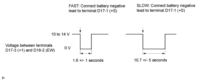


  1. Check the intermittent operation.

    1. Connect the voltmeter's positive (+) lead to terminal D17-3 (+1) and the negative (-) lead to terminal D18-2 (EW).

    2. Connect the battery's positive (+) lead to terminal D17-2 (+B) and the negative (-) lead to terminal D18-2 (EW) and D17-1 (+S).

    3. Turn the wiper switch to the INT position.

    4. Connect the battery's positive (+) lead to terminal D17-1 (+S) for 5 seconds.


    5. Connect the battery's negative (-) lead to terminal D17-1 (+S). Operate the intermittent wiper relay and check the voltage between terminals D17-3 (+1) and D18-2 (EW).

      OK:
      Voltage changes as shown in the illustration below.


      E152507E03

      If the result is not as specified, replace the switch assembly.
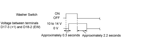


  1. Check the front washer operation.

    1. Turn the wiper switch OFF.

    2. Connect the battery's positive (+) lead to terminal D17-2 (+B) and the negative (-) lead to terminals D17-1 (+S) and D18-2 (EW).

    3. Connect the voltmeter's positive (+) lead to D17-3 (+1) and the negative (-) lead to terminal D18-2 (EW).


    4. Turn the washer switch ON and OFF, and check the voltage between terminals D17-3 (+1) and D18-2 (EW).

      OK:
      Voltage changes as shown in the illustration below.


      E125344E16

      If the result is not as specified, replace the switch assembly.


    E144464E13
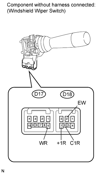
  1. Check the rear wiper switch.

    1. Measure the resistance according to the value(s) in the table below.

      Standard resistance:
      Tester Connection
      Switch Condition
      Specified Condition
      D18-2 (EW) - D18-6 (C1R)
      LO
      Below 1 Ω
      D18-2 (EW) - D18-7 (+1R)
      HI
      D18-2 (EW) - D18-6 (C1R)
      OFF
      10 kΩ or higher
      D18-2 (EW) - D18-7 (+1R)

      If the result is not as specified, replace the switch assembly.

  1. Check the rear washer switch.

    1. Measure the resistance according to the value(s) in the table below.

      Standard resistance:
      Tester Connection
      Switch Condition
      Specified Condition
      D18-2 (EW) - D17-5 (WR)
      ON
      Below 1 Ω
      OFF
      10 kΩ or higher

      If the result is not as specified, replace the switch assembly.