EXHAUST MANIFOLD > REMOVAL |
| 1. REMOVE FRONT WHEEL RH |
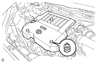
| 2. REMOVE V-BANK COVER SUB-ASSEMBLY |
![]() |
Hold the front of the V-bank cover and raise it to disengage the 2 clips on the front of the V-bank cover sub-assembly. Continue rising the V-bank cover sub-assembly to disengage the clip on the rear of the V-bank cover sub-assembly and remove the cover.
| 3. REMOVE ENGINE UNDER COVER ASSEMBLY |
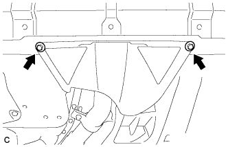
![]() |
Remove the 2 bolts and engine under cover assembly RR.
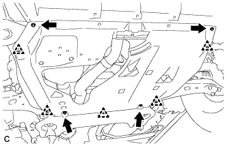
![]() |
Remove the 2 bolts, 2 screws, 5 clips and engine under cover assembly.
| 4. REMOVE NO. 1 ENGINE UNDER COVER |
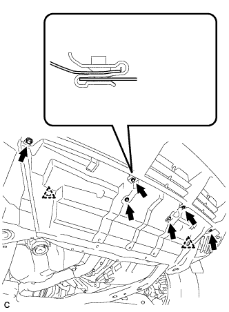
![]() |
Remove the 6 bolts, 2 clips and No. 1 engine under cover.
| 5. REMOVE NO. 2 ENGINE UNDER COVER |
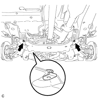
![]() |
Remove the 2 bolts and No. 2 engine under cover.
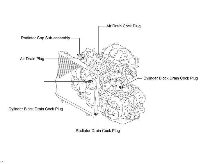
| 6. DRAIN ENGINE COOLANT |
Loosen the radiator drain cock plug.

Remove the radiator cap sub-assembly from the radiator assembly.
Loosen the 2 cylinder block drain cock plugs.
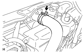
| 7. DISCONNECT NO. 1 RADIATOR HOSE |
![]() |
Disconnect the No. 1 radiator hose from the radiator.
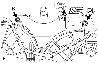
| 8. REMOVE RADIATOR RESERVE TANK ASSEMBLY |
![]() |
Disconnect the hose [A].
Remove the 2 bolts [B] and radiator reserve tank assembly.
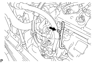
| 9. REMOVE NO. 2 OIL LEVEL DIPSTICK GUIDE |
![]() |
Remove the bolt and the No. 2 oil level dipstick guide.
| 10. REMOVE AIR FUEL RATIO SENSOR (for Bank 2 Sensor 1) |
![]() |
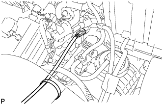
Disconnect the air fuel ratio sensor connector and remove the clamp.
![]() |
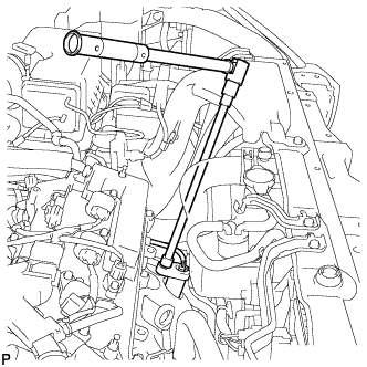
Using SST, remove the sensor from the exhaust manifold sub-assembly LH.
| 11. REMOVE NO. 2 EXHAUST MANIFOLD HEAT INSULATOR |
![]() |
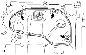
Remove the 3 bolts and No. 2 exhaust manifold heat insulator.
| 12. REMOVE PROPELLER WITH CENTER BEARING SHAFT ASSEMBLY (for 4WD) |
![]() |
Depress the brake pedal and hold it.
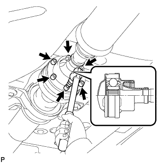
Using a hexagon wrench (6 mm), loosen the cross groove joint set bolts 1/2 turn.
![]() |
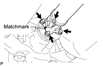
Place matchmarks on the rear propeller shaft and rear drive pinion flange sub-assembly.
Remove the 4 nuts, 4 bolts and 4 washers.
![]() |
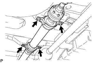
Remove the 4 bolts and 4 adjusting shims.
![]() |
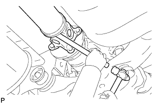
Using a brass bar and a hammer, remove the propeller shaft with center bearing shaft assembly.
![]() |
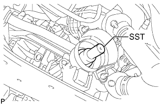
Insert SST into the transfer to prevent oil leakage.
| 13. REMOVE TAIL EXHAUST PIPE ASSEMBLY |
![]() |
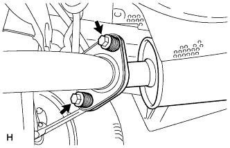
Remove the 2 bolts and 2 compression springs.
Disconnect the exhaust pipe support and remove the tail exhaust pipe assembly.
Remove the gasket from the center exhaust pipe assembly.
| 14. REMOVE CENTER EXHAUST PIPE ASSEMBLY |
![]() |
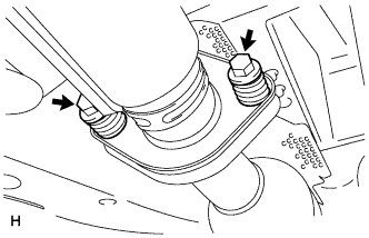
Remove the 2 bolts and 2 compression springs.
Disconnect the 3 exhaust pipe supports and remove the center exhaust pipe assembly.
Remove the gasket from the No. 3 exhaust pipe sub-assembly.
| 15. REMOVE FRONT NO. 3 EXHAUST PIPE SUB-ASSEMBLY |
![]() |
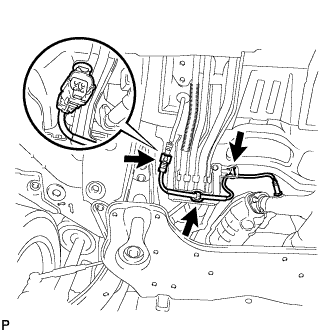
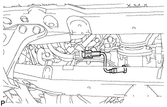
Remove the 3 clamps and disconnect the heated oxygen sensor (for bank 1 sensor 2) connector.
![]() |
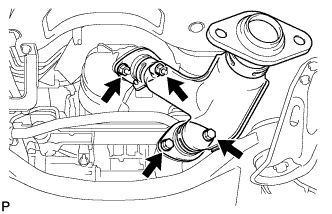
Remove the 2 bolts, 2 nuts and front No. 3 exhaust pipe sub-assembly.
Remove the 2 gaskets from the front No. 3 exhaust pipe sub-assembly.
| 16. REMOVE FRONT EXHAUST PIPE ASSEMBLY |
![]() |
Disconnect the heated oxygen sensor (for bank 2 sensor 2) connector.
![]() |
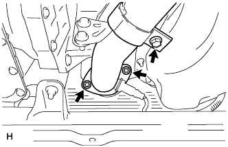
Loosen the bolt.
Remove the 2 nuts and front exhaust pipe assembly.
Remove the gasket from the front exhaust pipe assembly.
| 17. REMOVE NO. 2 MANIFOLD STAY |
![]() |
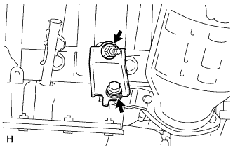
Remove the bolt, nut and No. 2 manifold stay.
| 18. REMOVE EXHAUST MANIFOLD SUB-ASSEMBLY LH |
![]() |
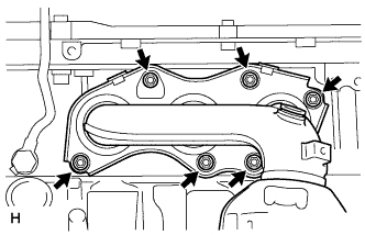
Remove the 6 nuts and exhaust manifold sub-assembly LH.
Remove the gasket.
| 19. REMOVE MANIFOLD STAY |
![]() |
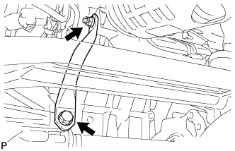
Remove the bolt, nut and manifold stay.
| 20. REMOVE EXHAUST MANIFOLD SUB-ASSEMBLY RH |
![]() |
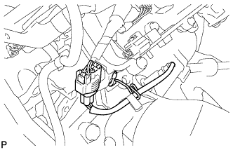
Disconnect the air fuel ratio sensor (for bank 1 sensor 1) connector and remove the clamp.
![]() |
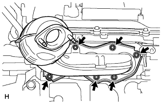
Remove the 6 nuts and exhaust manifold sub-assembly RH.
Remove the gasket.
| 21. REMOVE AIR FUEL RATIO SENSOR (for Bank 1 Sensor 1) |
![]() |
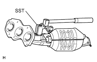
Using SST, remove the air fuel ratio sensor from the exhaust manifold sub-assembly RH.