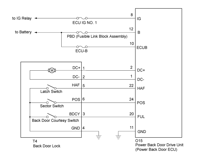
BACK DOOR CLOSER SYSTEM > Back Door Closer does not Operate |
| 1.CHECK BACK DOOR LOCK FUNCTION |
Check if the back door is fully closed by hand.
|
| ||||
| OK | |
 |
| 2.INITIALIZE POWER BACK DOOR ECU |
Check that the power back door drive unit (power back door ECU) can be initialized (Click here).
| NEXT | |
|
| 3.CHECK BACK DOOR CLOSER SYSTEM |
Check that the back door closer system operation.
|
| ||||
| OK | ||
 | ||
| ||
| 4.CHECK DTC OUTPUT |
Check for the DTCs (Click here).
| Result | Proceed to |
| DTC is not output | A |
| B2250 is output | B |
| B2251 is output | C |
|
| ||||
|
| ||||
| A | |
|
| 5.INSPECT FUSE (ECU IG NO. 1, ECU-B) |
Remove the ECU IG No. 1 fuse from the instrument panel junction block and ECU-B fuse from the engine room relay block.
Measure the resistance according to the value(s) in the table below.
| Tester Connection | Condition | Specified Condition |
| ECU IG NO. 1 | Always | Below 1 Ω |
| ECU-B | Always | Below 1 Ω |
|
| ||||
| OK | |
|
| 6.CHECK FUSIBLE LINK BLOCK ASSEMBLY (PBD FUSE) |
Remove the fusible link block assembly.
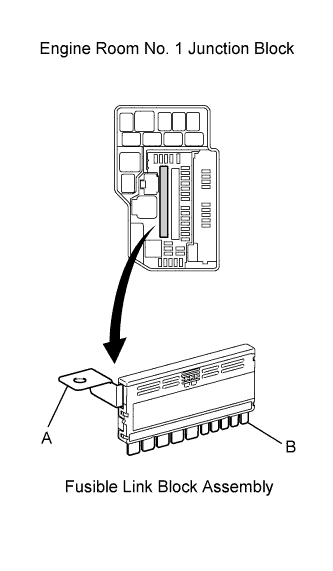 |
Measure the resistance according to the value(s) in the table below.
| Tester Connection | Condition | Specified Condition |
| A - B | Always | Below 1 Ω |
|
| ||||
| OK | |
|
| 7.CHECK HARNESS AND CONNECTOR (BODY GROUND) |
Disconnect the O15 power back door ECU connector.
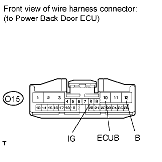 |
Measure the voltage according to the value(s) in the table below.
| Tester Connection | Condition | Specified Condition |
| O15-8 (IG) - Body ground | Ignition switch on (IG) | 11 to 14 V |
| O15-10 (ECUB) - Body ground | Always | 11 to 14 V |
| O15-12 (B) - Body ground | Always | 11 to 14 V |
|
| ||||
| OK | |
|
| 8.CHECK HARNESS AND CONNECTOR (POWER SOURCE) |
Disconnect the O15 power back door ECU connector.
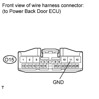 |
Measure the resistance according to the value(s) in the table below.
| Tester Connection | Condition | Specified Condition |
| O15-11 (GND) - Body ground | Always | Below 1 Ω |
|
| ||||
| OK | |
|
| 9.INSPECT BACK DOOR LOCK |
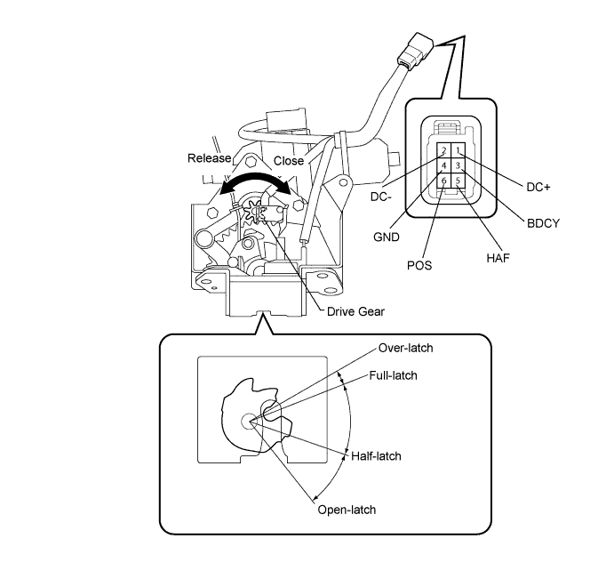
Remove the back door lock.
Apply battery voltage and check operation of the door lock motor.
| Measurement Condition | Specified Condition |
| Battery positive (+) → Terminal 1 (DC+) Battery negative (-) → Terminal 2 (DC-) | Latch turns to full-latch position |
| Battery positive (+) → Terminal 2 (DC-) Battery negative (-) → Terminal 1 (DC+) | Latch turns to open-latch position |
Measure the resistance of the switch.
| Tester Connection | Door Lock Latch Position | Specified Condition |
| 5 (HAF) - 4 (GND) | Over-latch | Below 1 Ω |
| 5 (HAF) - 4 (GND) | Open-latch | 10 kΩ or higher |
| 5 (HAF) - 4 (GND) | Full-latch | 10 kΩ or higher |
| 5 (HAF) - 4 (GND) | Half-latch | 10 kΩ or higher |
| Tester Connection | Door Lock Latch Position | Specified Condition |
| 3 (BDCY) - 4 (GND) | Open-latch | Below 1 Ω |
| 3 (BDCY) - 4 (GND) | Half-latch | Below 1 Ω |
| 3 (BDCY) - 4 (GND) | Full-latch | 10 kΩ or higher |
| 3 (BDCY) - 4 (GND) | Over-latch | 10 kΩ or higher |
|
| ||||
| OK | |
|
| 10.CHECK HARNESS AND CONNECTOR (BACK DOOR LOCK - POWER BACK DOOR ECU AND BODY GROUND) |
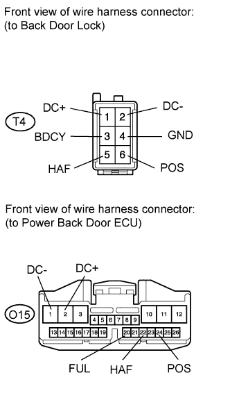 |
Disconnect the T4 door lock connector.
Disconnect the O15 ECU connector.
Measure the resistance according to the value(s) in the table below.
| Tester Connection | Condition | Specified Condition |
| T4-1 (DC+) - O15-2 (DC+) | Always | Below 1 Ω |
| T4-2 (DC-) - O15-1 (DC-) | Always | Below 1 Ω |
| T4-5 (HAF) - O15-22 (HAF) | Always | Below 1 Ω |
| T4-6 (POS) - O15-24 (POS) | Always | Below 1 Ω |
| T4-3 (BDCY) - O15-20 (FUL) | Always | Below 1 Ω |
| T4-4 (GND) - Body ground | Always | Below 1 Ω |
| T4-1 (DC+) - Body ground | Always | 10 kΩ or higher |
| T4-2 (DC-) - Body ground | Always | 10 kΩ or higher |
| T4-5 (HAF) - Body ground | Always | 10 kΩ or higher |
| T4-6 (POS) - Body ground | Always | 10 kΩ or higher |
| T4-3 (BDCY) - Body ground | Always | 10 kΩ or higher |
|
| ||||
| OK | ||
| ||
| ||

