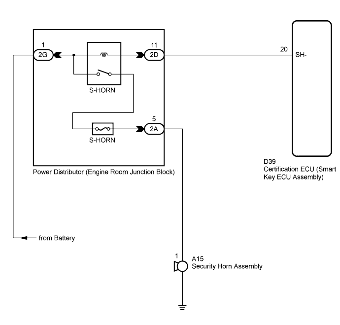
THEFT DETERRENT SYSTEM (w/ Smart Key System) > Security Horn Circuit |
| 1.CHECK HARNESS AND CONNECTOR (CERTIFICATION ECU - ENGINE ROOM JUNCTION BLOCK) |
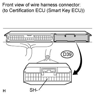 |
Disconnect the D39 ECU connector.
Connect the negative battery to the D39 ECU connector.
Check operation of the security horn.
| Measurement Condition | Specified Condition |
| Battery negative (-) → D39-20 (SH-) | Horn sounds |
|
| ||||
| OK | ||
 | ||
| ||
| 2.INSPECT SECURITY HORN ASSEMBLY |
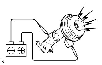 |
Remove the security horn assembly (Click here).
Check operation of the horn.
| Measurement Condition | Specified Condition |
| Battery positive (+) → Terminal 1 | Horn sounds |
| Battery negative (-) → Horn body |
|
| ||||
| OK | |
 |
| 3.CHECK HARNESS AND CONNECTOR (ENGINE ROOM JUNCTION BLOCK ASSEMBLY - SECURITY HORN ASSEMBLY) |
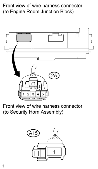 |
Disconnect the 2A engine room junction block assembly connector and A15 security horn connector.
Measure the resistance according to the value(s) in the table below.
| Tester Connection | Condition | Specified Condition |
| 2A-5 - A15-1 | Always | Below 1 Ω |
| 2A-5 - Body ground | Always | 10 kΩ or higher |
|
| ||||
| OK | |
|
| 4.CHECK HARNESS AND CONNECTOR (BATTERY - ENGINE ROOM JUNCTION BLOCK ASSEMBLY) |
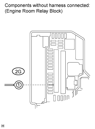 |
Disconnect the 2G engine room junction block assembly connector.
Measure the voltage on the relay block side according to the value(s) in the table below.
| Tester Connection | Condition | Specified Condition |
| 2G-1 - Body ground | Always | 11 to 14 V |
|
| ||||
| OK | |
|
| 5.CHECK HARNESS AND CONNECTOR (ENGINE ROOM JUNCTION BLOCK ASSEMBLY - CERTIFICATION ECU) |
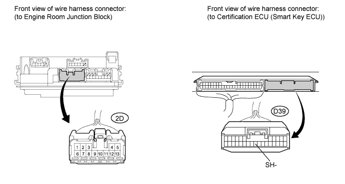
Disconnect the 2D engine room junction block assembly connector.
Disconnect the D39 ECU connector.
Measure the resistance according to the value(s) in the table below.
| Tester Connection | Condition | Specified Condition |
| 2D-11 - D39-20 (SH-) | Always | Below 1 Ω |
| D39-20 (SH-) - Body ground | Always | 10 kΩ or higher |
|
| ||||
| OK | ||
| ||
| ||

