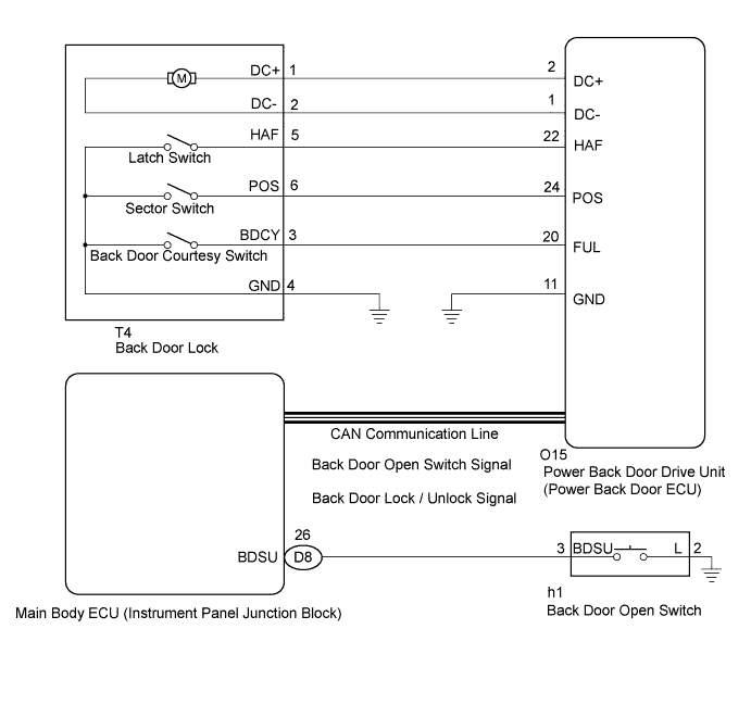
BACK DOOR CLOSER SYSTEM > Back Door cannot be Opened |
| 1.READ VALUE ON TECHSTREAM |
Check the Data List to determine if the back door lock function properly.
| Tester Display | Measurement Item/Range | Normal Condition | Diagnostic Note |
| Door Lock Status | Back door lock condition signal / LOCK or UNLOCK | LOCK: Back door is locked UNLOCK: Back door is unlocked | - |
|
| ||||
| OK | |
 |
| 2.READ VALUE ON TECHSTREAM |
Check the Data List to determine if the back door handle switch function properly.
| Tester Display | Measurement Item/Range | Normal Condition | Diagnostic Note |
| Back Door Open Handle SW | Back door opener switch / ON or OFF | ON: Back door opener switch is pushed OFF: Back door opener switch is not pushed | - |
|
| ||||
| OK | |
|
| 3.INSPECT BACK DOOR LOCK |
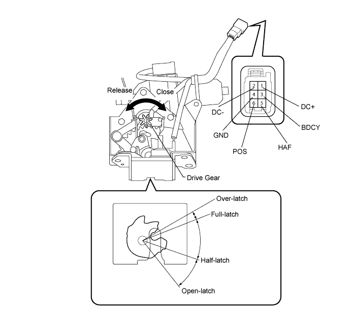
Remove the back door lock (Click here).
Apply battery voltage and check operation of the door lock motor.
| Measurement Condition | Specified Condition |
| Battery positive (+) → Terminal 1 (DC+) Battery negative (-) → Terminal 2 (DC-) | Latch turns to full-latch position |
| Battery positive (+) → Terminal 2 (DC-) Battery negative (-) → Terminal 1 (DC+) | Latch turns to open-latch position |
Measure the resistance of the switch.
| Tester Connection | Door Lock Latch Position | Specified Condition |
| 5 (HAF) - 4 (GND) | Over-latch | Below 1 Ω |
| 5 (HAF) - 4 (GND) | Open-latch | 10 kΩ or higher |
| 5 (HAF) - 4 (GND) | Full-latch | 10 kΩ or higher |
| 5 (HAF) - 4 (GND) | Half-latch | 10 kΩ or higher |
| Tester Connection | Door Lock Latch Position | Specified Condition |
| 6 (POS) - 4 (GND) | Open-latch | Below 1 Ω |
| 6 (POS) - 4 (GND) | Over-latch | 10 kΩ or higher |
| 6 (POS) - 4 (GND) | Full-latch | 10 kΩ or higher |
| 6 (POS) - 4 (GND) | Half-latch | 10 kΩ or higher |
| Tester Connection | Door Lock Latch Position | Specified Condition |
| 3 (BDCY) - 4 (GND) | Open-latch | Below 1 Ω |
| 3 (BDCY) - 4 (GND) | Half-latch | Below 1 Ω |
| 3 (BDCY) - 4 (GND) | Full-latch | 10 kΩ or higher |
| 3 (BDCY) - 4 (GND) | Over-latch | 10 kΩ or higher |
|
| ||||
| OK | |
|
| 4.CHECK HARNESS AND CONNECTOR (BACK DOOR LOCK - POWER BACK DOOR ECU) |
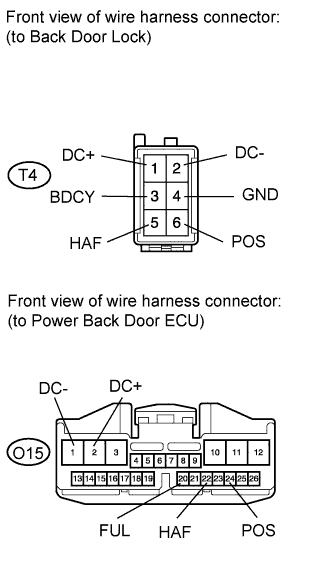 |
Disconnect the T4 back door lock connector.
Disconnect the O15 ECU connector.
Measure the resistance according to the value(s) in the table below.
| Tester Connection | Condition | Specified Condition |
| T4-1 (DC+) - O15-2 (DC+) | Always | Below 1 Ω |
| T4-2 (DC-) - O15-1 (DC-) | Always | Below 1 Ω |
| T4-5 (HAF) - O15-22 (HAF) | Always | Below 1 Ω |
| T4-6 (POS) - O15-24 (POS) | Always | Below 1 Ω |
| T4-3 (BDCY) - O15-20 (FUL) | Always | Below 1 Ω |
| T4-4 (GND) - Body ground | Always | Below 1 Ω |
| T4-1 (DC+) - Body ground | Always | 10 kΩ or higher |
| T4-2 (DC-) - Body ground | Always | 10 kΩ or higher |
| T4-5 (HAF) - Body ground | Always | 10 kΩ or higher |
| T4-6 (POS) - Body ground | Always | 10 kΩ or higher |
| T4-3 (BDCY) - Body ground | Always | 10 kΩ or higher |
|
| ||||
| OK | ||
 | ||
| ||
| 5.INSPECT BACK DOOR OPENER SWITCH |
Remove the back door opener switch (Click here).
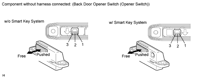
Measure the resistance according to the value(s) in the table below.
| Tester Connection | Switch Position | Specified Condition |
| 2 - 3 | Back door opener switch not pushed (OFF) | 10 kΩ or higher |
| 2 - 3 | Back door opener switch pushed (ON) | Below 1 Ω |
|
| ||||
| OK | |
|
| 6.CHECK HARNESS AND CONNECTOR (BACK DOOR OPENER SWITCH - MAIN BODY ECU) |
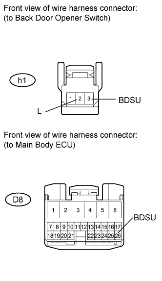 |
Disconnect the h1 switch connector.
Disconnect the D8 ECU connector.
Measure the resistance according to the value(s) in the table below.
| Tester Connection | Condition | Specified Condition |
| h1-3 (BDSU) - D8-26 (BDSU) | Always | Below 1 Ω |
| h1-2 (L) - Body ground | Always | Below 1 Ω |
| h1-3 (BDSU) - Body ground | Always | 10 kΩ or higher |
|
| ||||
| OK | ||
| ||
| ||
| 7.REPLACE POWER BACK DOOR DRIVE UNIT (POWER BACK DOOR ECU) |
Replace the power back door drive unit (power back door ECU) (Click here).
| NEXT | |
|
| 8.CHECK POWER BACK DOOR DRIVE UNIT (POWER BACK DOOR ECU) |
Check that the back door closer operates normally.
|
| ||||
| OK | ||
| ||
| ||

