 |
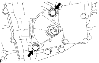
Loosen the 2 bolts of shift lever position sensor and move the shift lever to the N position.
SHIFT LEVER POSITION SENSOR > ADJUSTMENT |
| 1. ADJUST SHIFT LEVER POSITION SENSOR |
|
Loosen the 2 bolts of shift lever position sensor and move the shift lever to the N position.
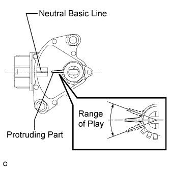 |
Align the protruding part and neutral basic line.
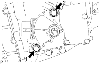 |
Tighten the 2 bolts in the order shown in the illustration.
| 2. INSPECT SHIFT LEVER POSITION SENSOR |
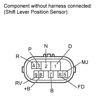 |
Measure the resistance according to the value(s) in the table below.
| 8 (+B) - 1 (D) | 8 (+B) - 2 (N) | 8 (+B) - 3 (P) | 8 (+B) - 4 (R) | 8 (+B) - 5 (MJ) | 8 (+B) - 6 (FD) | 8 (+B) - 7 (B) | 8 (+B) - 9 (RV) | |
| P position | 10 kΩ or higher | 4.2 to 5.1 kΩ | Below 1 Ω | 10 kΩ or higher | Below 1 Ω | 10 kΩ or higher | 10 kΩ or higher | 10 kΩ or higher |
| R position | 10 kΩ or higher | 4.2 to 5.1 kΩ | 10 kΩ or higher | Below 1 Ω | Below 1 Ω | 10 kΩ or higher | 10 kΩ or higher | Below 1 Ω |
| N position | 10 kΩ or higher | Below 1 Ω | 10 kΩ or higher | 10 kΩ or higher | Below 1 Ω | 10 kΩ or higher | 10 kΩ or higher | 10 kΩ or higher |
| D position | Below 1 Ω | 4.2 to 5.1 kΩ | 10 kΩ or higher | 10 kΩ or higher | Below 1 Ω | Below 1 Ω | 10 kΩ or higher | 10 kΩ or higher |
| B position | 10 kΩ or higher | 4.2 to 5.1 kΩ | 10 kΩ or higher | 10 kΩ or higher | Below 1 Ω | Below 1 Ω | Below 1 Ω | 10 kΩ or higher |