Home › HYBRID SYSTEM ยท P310 › HYBRID TRANSMISSION / TRANSAXLE › HYBRID VEHICLE TRANSAXLE

HYBRID VEHICLE TRANSAXLE > INSTALLATION

for Preparation Click here


1. INSTALL HYBRID VEHICLE TRANSAXLE ASSEMBLY
  1. Make sure that the knock pins are installed on the engine.


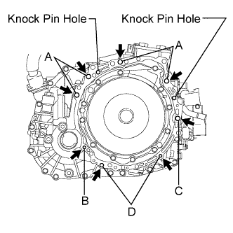
    C173146E01
  1. Install the hybrid vehicle transaxle and the 8 bolts shown in the illustration to the engine.

    Torque:
    Bolt A:
    64 N*m{ 653 kgf*cm , 47 ft.*lbf }
    Bolt B:
    46 N*m{ 469 kgf*cm , 34 ft.*lbf }
    Bolt C:
    64 N*m{ 653 kgf*cm , 47 ft.*lbf }
    Bolt D:
    37 N*m{ 377 kgf*cm , 27 ft.*lbf }

    NOTICE:
    1. Do not reuse bolt B.
    2. Do not forcibly pry out the hybrid vehicle transaxle assembly.
    3. Do not apply grease either to the spline or to the input shaft.


    Bolt
    Installation direction
    Diameter
    Bolt length
    A
    From transaxle to engine
    12 mm (0.47 in.)
    55 mm (2.17 in.)
    B
    From engine to transaxle
    10 mm (0.39 in.)
    55 mm (2.17 in.)
    C
    From transaxle to engine
    12 mm (0.47 in.)
    65 mm (2.56 in.)
    D
    From engine to transaxle
    10 mm (0.39 in.)
    33 mm (1.30 in.)


2. INSTALL NO. 1 TRANSMISSION CONTROL CABLE BRACKET
  1. Install the No. 1 transmission control cable bracket with 2 new bolts.

    Torque:
    12 N*m{ 120 kgf*cm , 9 ft.*lbf }


3. INSTALL OIL COOLER TUBE SUB-ASSEMBLY


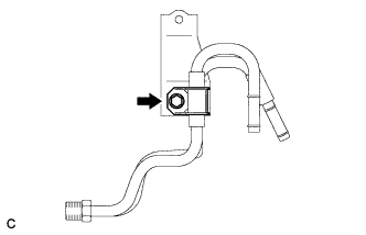
    C172977
  1. Install the oil cooler tube clamp with the bolt.

    Torque:
    8.2 N*m{ 84 kgf*cm , 73 in.*lbf }


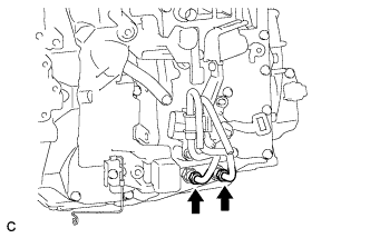
    C173269
  1. Using a union nut wrench 17 mm and a wrench, tighten the 2 new oil cooler tube.

    Torque:
    without Union nut wrench:
    34 N*m{ 350 kgf*cm , 25 ft.*lbf }
    with Union nut wrench:
    29 N*m{ 300 kgf*cm , 22 in.*lbf }

    NOTICE:
    1. Use a torque wrench with a fulcrum length of 180 mm (7.09 in.).
    2. This torque value is effective when the union nut wrench is parallel to a torque wrench.


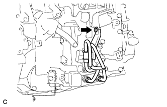
    C173270
  1. Install the tube support bracket with the bolt.

    Torque:
    8.2 N*m{ 84 kgf*cm , 73 in.*lbf }


4. INSTALL FRONT ENGINE MOUNTING BRACKET


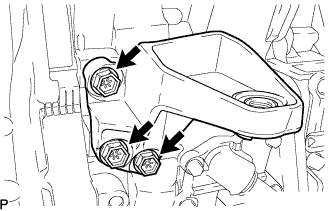
    C105752
  1. Install the front engine mounting bracket with the 3 bolts.

    Torque:
    64 N*m{ 653 kgf*cm , 47 ft.*lbf }


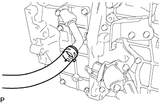
5. INSTALL WATER HOSE


    C105797
  1. Install the water hose with the clamp.


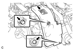
6. INSTALL AUTOMATIC TRANSMISSION CASE COVER


    C172750
  1. Install the transmission case cover with the bolt and clip.

    Torque:
    8.4 N*m{ 85 kgf*cm , 74 in.*lbf }

  1. Install the transmission control cable bracket with the bolt.

    Torque:
    12 N*m{ 122 kgf*cm , 9 ft.*lbf }


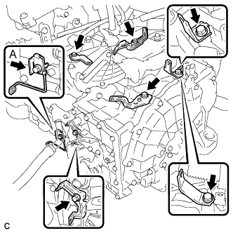
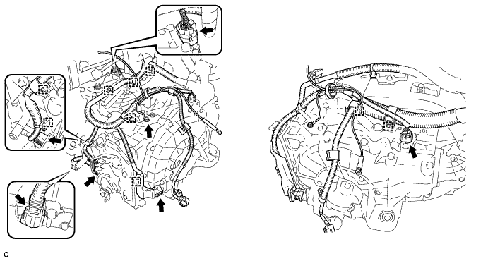
7. CONNECT ENGINE WIRE


    C172749E01
  1. Install the 7 wire harness brackets with the 7 bolts.

    Torque:
    Bolt A:
    29 N*m{ 296 kgf*cm , 21 ft.*lbf }
    Except Bolt A:
    8.4 N*m{ 86 kgf*cm , 74 in.*lbf }


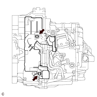
    C172748
  1. Install the transmission case cover with the 2 bolts.

    Torque:
    7.0 N*m{ 71 kgf*cm , 62 in.*lbf }


  1. Connect the connector.


    C172747

  1. Connect the wire harnesses to the wire harness clamp.

  1. Install the ground wire with the bolt.

    Torque:
    8.4 N*m{ 86 kgf*cm , 74 in.*lbf }


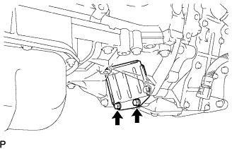
8. INSTALL FLYWHEEL HOUSING UNDER COVER


    C105748
  1. Install the flywheel housing under cover with the 2 bolts.

    Torque:
    10 N*m{ 102 kgf*cm , 7 ft.*lbf }


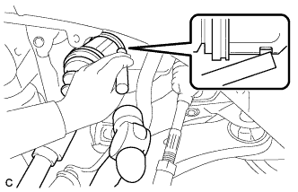
9. INSTALL FRONT DRIVE SHAFT ASSEMBLY LH


    C165536
  1. Align the shaft splines and install the drive shaft assembly LH with a brass bar and hammer.

    NOTICE:
    1. Set the shaft snap ring with the opening facing down.
    2. Be careful not to damage the drive shaft dust cover, boot, or oil seal.
    3. Move the drive shaft assembly while keeping it level.


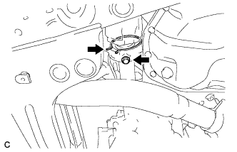
10. INSTALL FRONT DRIVE SHAFT ASSEMBLY RH
  1. Install the front drive shaft assembly RH.


    C167529
  1. Install a new bearing bracket hole snap ring and bolt.

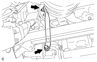
    Torque:
    32 N*m{ 326 kgf*cm , 24 ft.*lbf }

    NOTICE:
    1. Do not damage the boot or oil seal.
    2. Move the drive shaft assembly while keeping it level.


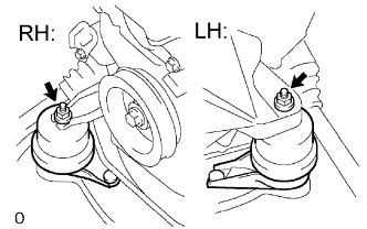
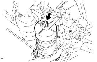
11. INSTALL FRONT FRAME ASSEMBLY


    A078403E09
  1. Install the engine mounting insulators RH and LH with the 2 nuts.

    Torque:
    95 N*m{ 969 kgf*cm , 70 ft.*lbf }


    A108133
  1. Install the front engine mounting insulator with the nut.

    Torque:
    87 N*m{ 887 kgf*cm , 64 ft.*lbf }


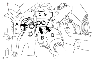
12. INSTALL REAR ENGINE MOUNTING INSULATOR


    A175947E01
  1. Install the rear engine mounting insulator with the 3 bolts.

    Torque:
    Bolt A:
    130 N*m{ 1326 kgf*cm , 96 ft.*lbf }
    Bolt B:
    75 N*m{ 765 kgf*cm , 55 ft.*lbf }


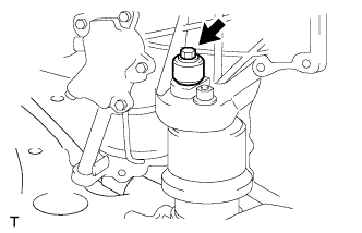
13. INSTALL HYBRID TRANSAXLE MASS DAMPER


    A109817
  1. Install the bolt and transaxle mass damper.

    Torque:
    14 N*m{ 138 kgf*cm , 10 ft.*lbf }


14. INSTALL MANIFOLD STAY


    A176007
  1. Install the manifold stay with the bolt and nut.

    Torque:
    34 N*m{ 348 kgf*cm , 25 ft.*lbf }


15. INSTALL ENGINE ASSEMBLY WITH HYBRID VEHICLE TRANSAXLE
(Click here)