 |
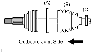
Install new parts to the outboard joint shaft assembly in the following order.
No. 2 rear drive shaft outboard joint boot clamp (A)
Outboard joint boot (B)
Rear drive shaft outboard joint boot clamp (C)
REAR DRIVE SHAFT > REASSEMBLY |
| 1. INSTALL OUTBOARD JOINT BOOT |
|
Install new parts to the outboard joint shaft assembly in the following order.
No. 2 rear drive shaft outboard joint boot clamp (A)
Outboard joint boot (B)
Rear drive shaft outboard joint boot clamp (C)
Pack the outboard joint shaft and outboard joint boot with grease.
| 2. INSTALL REAR DRIVE SHAFT OUTBOARD JOINT BOOT CLAMP |
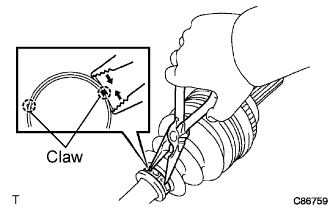 |
Using needle nose pliers, install the rear drive shaft outboard joint boot clamp as shown in the illustration.
| 3. INSTALL NO. 2 REAR DRIVE SHAFT OUTBOARD JOINT BOOT CLAMP |
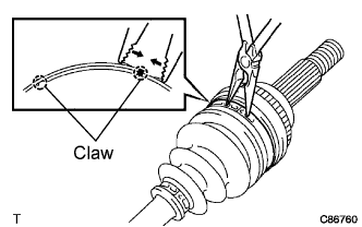 |
Using needle nose pliers, install the No. 2 rear drive shaft outboard joint boot clamp as shown in the illustration.
| 4. INSTALL REAR DRIVE SHAFT INBOARD JOINT ASSEMBLY |
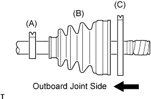 |
Install new parts to the outboard joint shaft assembly in the following order.
Rear drive shaft inboard joint boot clamp (A)
Inboard joint boot (B)
No. 2 rear drive shaft inboard joint boot clamp (C)
Install the cage to the rear drive outboard joint shaft assembly.
Hold the rear drive outboard joint shaft assembly between aluminium plates in a vise.
Align the matchmarks.
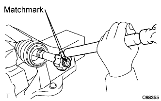 |
Using a brass bar and hammer, tap in the inner race to the outboard joint shaft assembly.
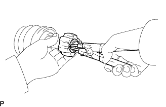 |
Using a snap ring expander, install a new snap ring.
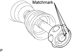 |
Align the matchmarks and install the cage to the inner race.
Apply grease to the 6 balls.
Install the 6 balls.
Pack the inboard joint assembly and inboard joint boot with grease.
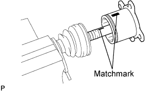 |
Align the matchmarks, install the rear drive shaft inboard joint assembly to the outboard joint shaft assembly.
| 5. INSTALL INBOARD JOINT BOOT |
Install the inboard joint boot to the rear drive shaft inboard joint assembly.
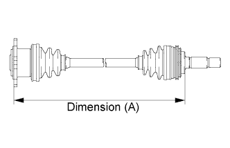 |
Check whether the drive shaft dimensions are within the following specifications.
| 6. INSTALL REAR DRIVE SHAFT INBOARD JOINT BOOT CLAMP |
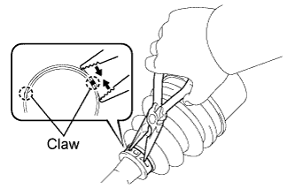 |
Using needle nose pliers, install the rear drive shaft inboard joint boot clamp as shown in the illustration.
| 7. INSTALL NO. 2 REAR DRIVE SHAFT INBOARD JOINT BOOT CLAMP |
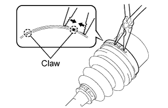 |
Using needle nose pliers, install the No. 2 rear drive shaft inboard joint boot clamp as shown in the illustration.
| 8. INSPECT REAR DRIVE SHAFT ASSEMBLY |