HV RELAY ASSEMBLY > INSPECTION |
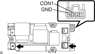
| 1. INSPECT SMR1 AND SYSTEM MAIN RESISTOR |
![]() |
Measure the resistance according to the value(s) in the table below.
| Tester Connection | Condition | Specified Condition |
| 3 (CON1) - 4 (GND) | -31°F (-35°C ) to 176°F (80°C) | 70 to 165 Ω |
| HV battery side positive connector terminals - Inverter with converter assembly side of junction block positive terminal | Battery voltage is not applied between terminals 3 (CON1) and 4 (GND) | 10 kΩ or more |
| Terminals of the HV battery side positive connector - Inverter with converter assembly HV battery side positive terminal | Battery voltage is applied between terminals 3 (CON1) and 4 (GND) | 28.5 to 31.5 Ω |
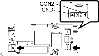
| 2. INSPECT SMR2 |
![]() |
Measure the resistance according to the value(s) in the table below.
| Tester Connection | Condition | Specified Condition |
| 1 (CON2) - 4 (GND) | -31°F (-35°C ) to 176°F (80°C) | 20 to 60 Ω |
| Terminals of the HV battery side positive connector - Inverter with converter assembly HV battery side positive terminal | Battery voltage is not applied between terminals 1 (CON2) and 4 (GND) | 10 kΩ or more |
| Terminals of the HV battery side positive connector - Inverter with converter assembly HV battery side positive terminal | Battery voltage is applied between terminals 1 (CON2) and 4 (GND) | Below 1 Ω |
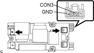
| 3. INSPECT SMR3 |
![]() |
Measure the resistance according to the value(s) in the table below.
| Tester Connection | Condition | Specified Condition |
| 2 (CON3) - 4 (GND) | -31°F (-35°C ) to 176°F (80°C) | 20 to 60 Ω |
| Terminals of the HV battery side positive connector - Inverter with converter assembly HV battery side positive terminal | Battery voltage is not applied between terminals 2 (CON3) and 4 (GND) | 10 kΩ or more |
| Terminals of the HV battery side negative connector - Inverter with converter assembly HV battery side negative terminal | Battery voltage is applied between terminals 2 (CON3) and 4 (GND) | Below 1 Ω |