ELECTRONICALLY CONTROLLED BRAKE SYSTEM > FAIL-SAFE CHART |
| FAIL-SAFE FUNCTION |
If a malfunction occurs in the skid control ECU, sensor signal, or actuator, the remaining functioning components will maintain brake control.
When trouble occurs in the brake control system, the skid control ECU turns the warning light on, and prohibits ABS, BA, and VSC operations.
| Malfunctioning Area | Control Method |
| ABS system | ABS, BA, TRAC and VSC control prohibited |
| BA system | ABS, BA, TRAC and VSC control prohibited |
| EBD system | ABS, EBD, BA, TRAC and VSC control prohibited |
| Malfunctioning Area | Control Method |
| Hybrid control system (TRAC and VSC systems) | Before control: Disables control During control: Uses only the brakes to effect control |
| Brake control system (TRAC and VSC systems) | Before control: Disables control During control: Disables control (by gradually ending control) |
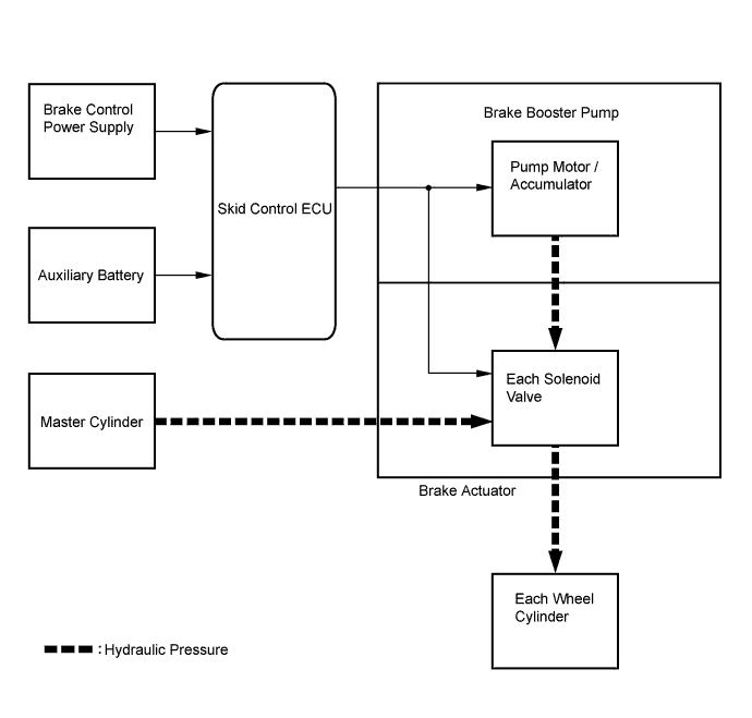
The skid control ECU prevents operation of a malfunctioning hydraulic system and continues brake control with a backup hydraulic system.
If the brake control is stopped under such conditions as when trouble occurs with a hydraulic pressure source, the pressure generated in the master cylinder by the driver is applied to the front wheel cylinders to ensure braking force.
A power back-up unit is built in as an additional power source to supply stable power to the system.
If the regenerative brake alone does not operate under such conditions as a communication error with the hybrid vehicle control ECU, control is switched so that all braking force is generated with hydraulic braking pressure.
| Malfunctioning Area | Generated Braking Force |
| Skid control ECU | Normally operating parts will control brake and generated braking force |
| Hydraulic pressure controlling parts | Normally operating parts will control brake and generated braking force |
| Hydraulic pressure source | Braking force generated by the driver |