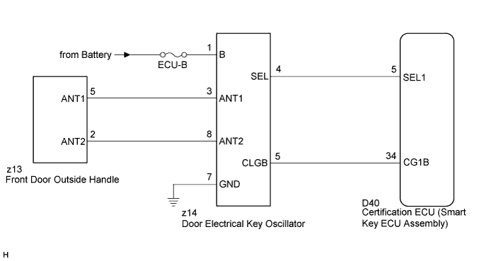
SMART KEY SYSTEM > Driver Side Door Entry Lock and Unlock Functions do not Operate |
| 1.CHECK POWER DOOR LOCK OPERATION |
When the door control switch on the master switch assembly is operated, check that the locked doors unlock (Click here).
|
| ||||
| OK | |
 |
| 2.READ VALUE ON TECHSTREAM (DOOR OUTSIDE HANDLE) |
Connect the Techstream to the DLC3.
Turn the power switch on (IG).
Turn the Techstream on.
Enter the following menus:
Body Electrical / Smart Key / Data List.
Select D-Door Touch Sensor or D-Door Trigger Switch in the Data List and read the Techstream display.
| Tester Display | Measurement Item/Range | Normal Condition | Diagnostic Note |
| D-Door Touch Sensor | Driver side door touch sensor / ON or OFF | ON: Touch sensor is touched OFF: Touch sensor is not touched | - |
| D-Door Trigger Switch | Driver side door lock switch / ON or OFF | ON: Entry lock switch is pressed OFF: Entry lock switch is not pressed | - |
|
| ||||
| OK | |
|
| 3.CHECK WAVE ENVIRONMENT |
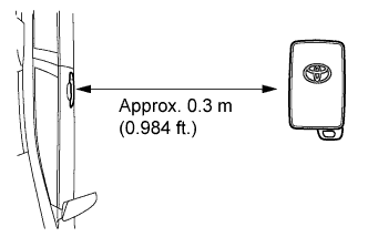 |
Bring the electrical key transmitter near the driver door outside handle, and perform a driver door entry lock and unlock operation check.
|
| ||||
| OK | ||
 | ||
| ||
| 4.PERFORM KEY DIAGNOSTIC MODE INSPECTION |
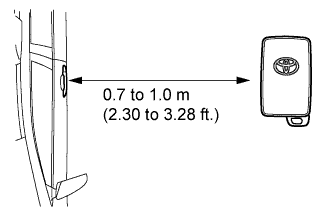 |
Diagnostic mode inspection (driver door electrical key oscillator)
Connect the Techstream to the DLC3.
Turn the power switch on (IG).
Turn the Techstream on.
Enter the following menus:
Body Electrical / Smart Key / Utility / Communication Check (Key Diag Mode) / Overhead + Driver Side.
When the electrical key transmitter is in the position shown in the illustration, check that the wireless door lock buzzer sounds.
|
| ||||
| OK | ||
| ||
| ||
| 5.CHECK HARNESS AND CONNECTOR (CERTIFICATION ECU - DOOR ELECTRICAL KEY OSCILLATOR) |
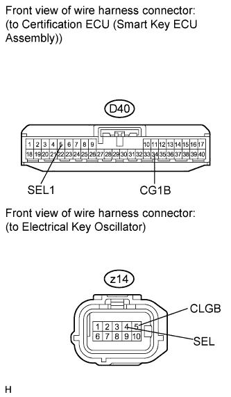 |
Disconnect the certification ECU (smart key ECU assembly) and door electrical key oscillator connectors.
Measure the resistance according to the value(s) in the table below.
| Tester Connection | Condition | Specified Condition |
| D40-5 (SEL1) - z14-4 (SEL) | Always | Below 1 Ω |
| D40-34 (CG1B) - z14-5 (CLGB) | Always | Below 1 Ω |
| D40-5 (SEL1) - Body ground | Always | 10 kΩ or higher |
| D40-34 (CG1B) - Body ground | Always | 10 kΩ or higher |
|
| ||||
| OK | |
|
| 6.CHECK HARNESS AND CONNECTOR (DOOR ELECTRICAL KEY OSCILLATOR - FRONT DOOR OUTSIDE HANDLE) |
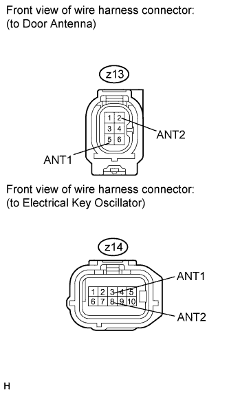 |
Remove the front door outside handle (Click here).
Disconnect the door antenna connector.
Measure the resistance according to the value(s) in the table below.
| Tester Connection | Condition | Specified Condition |
| z13-2 (ANT2) - z14-8 (ANT2) | Always | Below 1 Ω |
| z13-5 (ANT1) - z14-3 (ANT1) | Always | Below 1 Ω |
| z13-2 (ANT2) - Body ground | Always | 10 kΩ or higher |
| z13-5 (ANT1) - Body ground | Always | 10 kΩ or higher |
|
| ||||
| OK | |
|
| 7.INSPECT FUSE (ECU-B) |
Remove the ECU-B fuse from the engine room junction block.
Measure the resistance according to the value(s) in the table below.
| Tester Connection | Condition | Specified Condition |
| ECU-B fuse | Always | Below 1 Ω |
|
| ||||
| OK | |
|
| Go to step 9 |
| 8.CHECK HARNESS AND CONNECTOR (DOOR ELECTRICAL KEY OSCILLATOR - BATTERY AND BODY GROUND) |
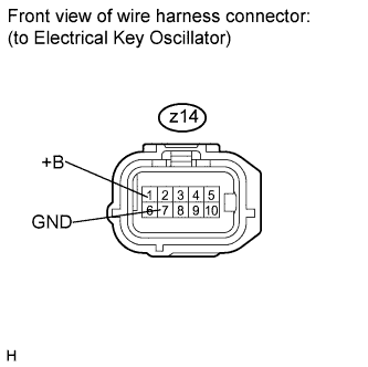 |
Measure the voltage according to the value(s) in the table below.
| Tester Connection | Condition | Specified Condition |
| z14-1 (+B) - z14-7 (GND) | Always | 11 to 14 V |
|
| ||||
| OK | |
|
| 9.REPLACE DOOR ELECTRICAL KEY OSCILLATOR |
Replace the door electrical key oscillator (Click here).
| NEXT | |
|
| 10.CHECK DOOR ELECTRICAL KEY OSCILLATOR (OPERATION) |
Check that the entry functions operate normally.
|
| ||||
| OK | ||
| ||
| ||

