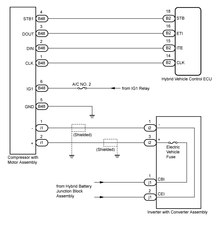
DTC B1475/75 A/C Inverter Cooling / Heating System Malfunction |
| DTC No. | DTC Detection Condition | Trouble Area |
| B1475/75 | Temperature in the inverter is outside the specified range (temperature is too high), or there is an open or short to ground in the temperature sensor circuit. |
|
| 1.CHECK CAN COMMUNICATION SYSTEM |
Using the Techstream, check if the CAN communication system is functioning normally.
| Result | Proceed to |
| CAN DTC is not output | A |
| CAN DTC is output | B |
|
| ||||
| A | |
 |
| 2.PERFORM ACTIVE TEST USING TECHSTREAM |
Connect the Techstream to the DLC3.
Turn the power switch on (IG) and turn the Techstream on.
Select the item below in the Active Test and then check that the fan operates.
| Tester Display | Test Part | Control Range | Diagnostic Note |
| Electrical Fan | Electrical fan | OFF, ON | - |
|
| ||||
| OK | |
|
| 3.CHECK REFRIGERANT PRESSURE |
Install a manifold gauge set .
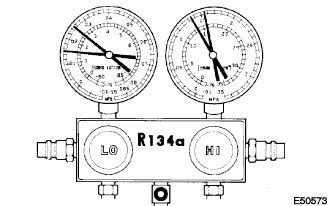 |
Read the manifold gauge pressure when the following conditions are established.
Prepare the vehicle according to the chart below.
| Item | Condition |
| Vehicle doors | All fully open |
| Temperature setting | MAX COLD |
| Blower speed | HI |
| A/C switch | ON |
| Recirculation/Fresh switch | RECIRCULATION (30 to 35°C (86 to 95°F)) |
|
| ||||
| OK | |
|
| 4.READ OUTPUT DTC (DTC B1475/75) |
Clear the DTCs (Click here).
Prepare the vehicle according to the table below.
| Item | Condition |
| Blower speed | HI |
| A/C switch | ON |
| Temperature setting | MAX. COLD |
Check for DTCs (Click here).
| Result | Proceed to |
| DTC B1475/75 is not output (normal) | A |
| DTC B1475/75 is output | B |
|
| ||||
| A | ||
 | ||
| ||
