DTC P1451 Fuel Tank Pressure Sensor Range/Performance |
DTC P1452 Fuel Tank Pressure Sensor Low Input |
DTC P1453 Fuel Tank Pressure Sensor High Input |
| DTC No. | Monitoring Item | DTC Detection Condition | Trouble Area | Detection Timing | Detection Logic |
| P1451 | Pressure sensor abnormal voltage fluctuation | Sensor output voltage fluctuates frequently in certain time period. |
|
| 2 trip |
| P1451 | Pressure sensor constant voltage | Sensor output voltage does not vary in certain time period. |
| EVAP monitoring (power switch off) | 2 trip |
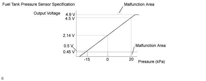
| P1452 | Pressure sensor voltage low | Fuel tank pressure is less than -17.187 kPa (-128.93 mmHg) for 0.5 seconds. |
|
| 1 trip |
| P1453 | Pressure sensor voltage high | Fuel tank pressure is more than 23.9 kPa (179.30 mmHg) for 0.5 seconds. |
|
| 1 trip |

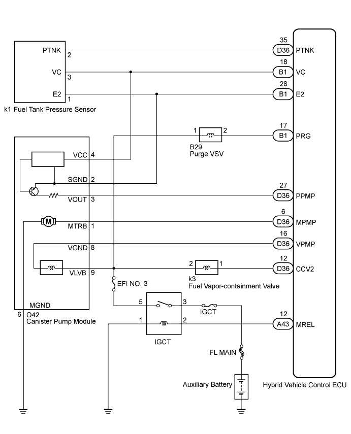
| Required Sensors/Components | Canister pump module |
| Frequency of Operation | Once per driving cycle: P1451 sensor constant voltage Continuous: P1451 sensor abnormal voltage fluctuation, P1452 and P1453 |
| Duration | 0.5 seconds: P1452, P1453 Within 15 seconds: P1451 |
| MIL Operation | Immediate: P1452, P1453 2 driving cycles: P1451 |
| Sequence of Operation | None |
| Monitor runs whenever following DTCs are not present | None |
| Fuel tank pressure | -15 kPa (-113 mmHg) or more and less than 20 kPa (150 mmHg) |
| Battery voltage | 10.5 V or more |
| Intake air temperature | 4.4 to 35°C (40 to 95°F) |
| EVAP pressure sensor malfunction (P1450, P1452, P1453) | Not detected |
| Either of the following conditions is met | A or B |
| A. Engine | Running |
| B. Soak time (power switch off time) | 5 hours |
| First time | 7 hours |
| Second time | 9 hours and 30 minutes |
| Atmospheric pressure | Less than 70 kPa (525 mmHg) or 110 kPa (825 mmHg) or more |
| Battery voltage | 10.5 V or more |
| Intake air temperature | 4.4 to 35°C (40 to 95°F) |
| EVAP pressure sensor malfunction (P1450, P1452, P1453) | Not detected |
| Soak time (power switch off time) | 5 hours |
| First time | 7 hours |
| Second time | 9 hours and 30 minutes |
| The monitor will run whenever these DTCs are not present | None |
| Battery voltage | 8 V or more |
| Frequency that fuel tank pressure change is 0.3 kPa or more | 10 times or more in 10 seconds |
| Fuel tank pressure change during reference pressure measurement | Less than 0.35 kPa (2.63 mmHg) |
| Fuel tank pressure | Less than -17.187 kPa (-128.93 mmHg) |
| Fuel tank pressure | More than 23.9 kPa (179.30 mmHg) |

| 1.CONFIRM DTC AND FUEL TANK PRESSURE |
Connect the Techstream to the DLC3.
Turn the power switch on (IG).
Turn the Techstream on.
Enter the following menus: Powertrain / Engine and ECT / Trouble Codes.
Read the DTCs.
Enter the following menus: Powertrain / Engine and ECT / Data List.
Read the EVAP (Evaporative Emission) pressure displayed on the Techstream.
| Display (DTC Output) | Test Result | Suspected Trouble Area | Proceed to |
| P1451 | - | Pressure sensor | C |
| P1450 and/or P1452 | Less than -17.187 kPa (-128.93 mmHg) |
| A |
| P1450 and/or P1453 | More than 23.5 kPa (176.69 mmHg) |
| B |
|
| ||||
|
| ||||
| A | |
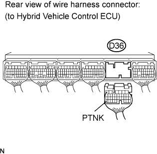
| 2.CHECK HARNESS AND CONNECTOR (FUEL TANK PRESSURE SENSOR - HYBRID VEHICLE CONTROL ECU) |
![]() |
Turn the power switch off.
Disconnect the hybrid vehicle control ECU connector.
Measure the resistance between the PTNK terminal of the hybrid vehicle control ECU connector and body ground.
| Test Result | Suspected Trouble Area | Proceed to |
| 10 Ω or less |
| A |
| 10 kΩ or more |
| B |
Reconnect the hybrid vehicle control ECU connector.
|
| ||||
| A | |
| 3.CHECK HARNESS AND CONNECTOR (FUEL TANK PRESSURE SENSOR - HYBRID VEHICLE CONTROL ECU) |
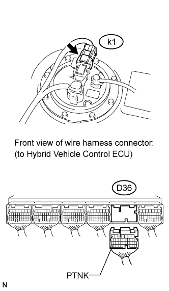
![]() |
Remove the fuel tank assembly.
Disconnect the fuel tank pressure sensor connector.
Disconnect the hybrid vehicle control ECU connector.
Measure the resistance between the PTNK terminal of the hybrid vehicle control ECU connector and body ground.
| Test Result | Suspected Trouble Area | Proceed to |
| 10 kΩ or more | Short in pressure sensor circuit | A |
| 10 Ω or less | Short in wire harness/connector (hybrid vehicle control ECU - pressure sensor) | B |
Reconnect the pressure sensor connector.
Reconnect the hybrid vehicle control ECU connector.
|
| ||||
|
| ||||
| 4.CHECK HARNESS AND CONNECTOR (FUEL TANK PRESSURE SENSOR - HYBRID VEHICLE CONTROL ECU) |
![]() |
Remove the fuel tank assembly.
Disconnect the fuel tank pressure sensor connector.
Turn the power switch on (IG).
Measure the voltage and resistance according to the value(s) in the table below.
| Tester Connection | Specified Condition |
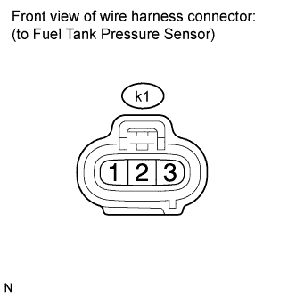
| k1-3 - Body ground | 4.5 to 5.0 V |
| k1-2 - Body ground | 100 Ω or less |
| Test Result | Suspected Trouble Area | Proceed to |
| Voltage and resistance within standard ranges | Open in pressure sensor circuit | A |
| Voltage and resistance outside standard ranges | Open in wire harness/connector (hybrid vehicle control ECU - pressure sensor) | B |
Reconnect the canister connector.
|
| ||||
| A | |
| 5.REPLACE FUEL TANK PRESSURE SENSOR |
Replace the fuel tank pressure sensor (Click here).
|
| ||||
| 6.REPAIR OR REPLACE HARNESS OR CONNECTOR |
|
| ||||
| 7.REPLACE HYBRID VEHICLE CONTROL ECU |
Replace the hybrid vehicle control ECU (Click here).
|
| ||||
| 8.CHECK WHETHER DTC OUTPUT RECURS (AFTER REPAIR) |
Connect the Techstream to the DLC3.
Turn the power switch on (IG) and turn the Techstream on.
Wait for at least 60 seconds.
Enter the following menus: Powertrain / Engine and ECT / Trouble Codes.
| NEXT | ||
| ||