Home › ENGINE › 3MZ-FE ENGINE CONTROL SYSTEM › SFI SYSTEM

DTC    P3190    Poor Engine Power

DTC    P3191    Engine does not Start

DTC    P3193    Fuel Run Out

for Preparation Click here


DESCRIPTION

From the hybrid vehicle ECU, the ECM (Included in hybrid vehicle control ECU) receives data such as power output required for the engine (required output), estimated torque produced by the engine (estimated torque), engine RPM of control target (target RPM), whether the engine is in start mode or not. Then, based on the required output and target RPM, the ECM (Included in hybrid vehicle control ECU) calculates a target torque that is to be produced by the engine and compares it with the estimated torque. If the estimated torque is very low compared with the target torque, or the engine start mode continues for the specific duration calculated by water temperature, an abnormal condition is detected.

DTC No.
DTC Detection Condition
Trouble Area
P3190
Following conditions continue at a fixed engine RPM or a fixed length of time:
  1. Communication with hybrid vehicle control ECU is normal
  2. Engine RPM is a fixed value or more
  3. Engine start mode is not activated
  4. Target torque is a fixed value
  5. Ratio of estimated torque against target torque is less than 20%
  1. Intake system
  2. Throttle body
  3. Fuel pressure
  4. Engine
  5. Mass air flow meter
  6. Out of fuel
  7. Engine coolant temperature sensor
  8. Crankshaft position sensor
  9. Camshaft position sensor
  10. Hybrid vehicle control ECU
P3191
Following conditions continue at a fixed engine RPM or a fixed length of time:
  1. Communication with hybrid vehicle control ECU is normal
  2. Engine RPM is a fixed value or more
  3. Engine start mode is activated
  1. Intake system
  2. Throttle body
  3. Fuel pressure
  4. Engine
  5. Mass air flow meter
  6. Out of fuel
  7. Engine coolant temperature sensor
  8. Crankshaft position sensor
  9. Camshaft position sensor
  10. Hybrid vehicle control ECU
P3193
Following conditions are met:
  1. Fuel low level signal input into ECM (included in the hybrid vehicle control ECU)
  2. Detection condition for P3190 or P3191 is satisfied
  1. Out of fuel
  2. Hybrid vehicle control ECU

MONITOR DESCRIPTION

The ECM (included in the hybrid vehicle control ECU) and hybrid vehicle control ECU are connected by a communication line called CAN. The ECM (Included in hybrid vehicle control ECU) sends information on the engine speed and other data to the hybrid vehicle control ECU while the hybrid vehicle control ECU sends the information such as a requirement for the engine power to the ECM (Included in hybrid vehicle control ECU) using tha CAN communication line. When the communication between the ECM (Included in hybrid vehicle control ECU) and hybrid vehicle control ECU is normal and the following items become specific condition, the ECM (Included in hybrid vehicle control ECU) will illuminate the MIL and set a DTC.
  1. Engine speed
  2. Power switch
  3. Target torque
  4. Ratio of target torque against estimated torque
  5. Fuel level

MONITOR STRATEGY


Related DTCs
P3190: Poor engine power
P3191: Engine does not start
P3193: Fuel run out
Required sensors/components
Main sensors: Crankshaft position sensor
Related sensors: Hybrid vehicle control ECU
Frequency of operation
Continuous
Duration
100 engine revolutions and 6 seconds
MIL operation
Immediately
Sequence of operation
None

TYPICAL ENABLING CONDITIONS


Monitor runs whenever following DTCs are not present
None
Fuel cut operation
Not operated
Engine RPM
650 rpm or more (varies with engine coolant temperature)

TYPICAL MALFUNCTION THRESHOLDS


Case1: P3190 
Time for low engine torque
100 engine revolutions or more, and 6 seconds or more
(varies with engine coolant temperature)
Fuel sender gauge output
0.02 V or more

Case2: P3191 
Engine start no-determination time (receive from hybrid vehicle ECU)
100 engine revolutions or more, and 6 seconds or more
(varies with engine coolant temperature)
Fuel sender gauge output
0.02 V or more

Case3: P3193 
Time for low engine torque or Engine start no-determination time
100 engine revolutions or more, and 6 seconds or more
(varies with engine coolant temperature)
Fuel sender gauge output
Less than 0.02 V

INSPECTION PROCEDURE

HINT:
Read freeze frame data using the Techstream. The ECM (included in the hybrid vehicle control ECU) records vehicle and driving condition information as freeze frame data the moment a DTC is stored. When troubleshooting, freeze frame data can be helpful in determining whether the vehicle was running or stopped, whether the engine was warmed up or not, whether the air-fuel ratio was lean or rich, as well as other data recorded at the time of a malfunction.

1.CHECK ANY OTHER DTCS OUTPUT (IN ADDITION TO DTC P3190, P3191 AND/OR P3193)
  1. Connect the Techstream to the DLC3.

  1. Turn the power switch on (IG).

  1. Turn the Techstream on.

  1. On the Techstream, select the items: Powertrain / Engine and ECT / Trouble Codes.

  1. Read the DTCs using the Techstream.

    Result:

    Display (DTC output)
    Proceed to
    P3190, P3191 and/or P3193
    A
    P3190, P3191 and/or P3193, and other DTCs
    B

    HINT:
    If any codes other than P3190, P3191 and/or P3193 are output, perform troubleshooting for those DTCs first.


B
GO TO DTC CHART
A


2.CHECK SHORTAGE OF FUEL


NG
REFILL FUEL
OK


3.CHECK INTAKE SYSTEM

OK:
The air induction system has no leakage and blockages.


NG
REPAIR OR REPLACE INTAKE SYSTEM
OK


4.CHECK FOR UNUSUAL NOISE OR VIBRATION WHEN STARTING ENGINE OR REVVING UP

OK:
Unusual noise and vibration do not occur.


NG
REPAIR OR REPLACE MALFUNCTIONING PART
OK


5.CHECK FUEL PRESSURE
  1. Check the fuel pressure .


NG
CHECK AND REPLACE FUEL SYSTEM
OK


6.INSPECT MASS AIR FLOW METER ASSEMBLY
  1. Inspect the mass air flow meter (Click here).


NG
REPLACE MASS AIR FLOW METER ASSEMBLY (Click here)
OK


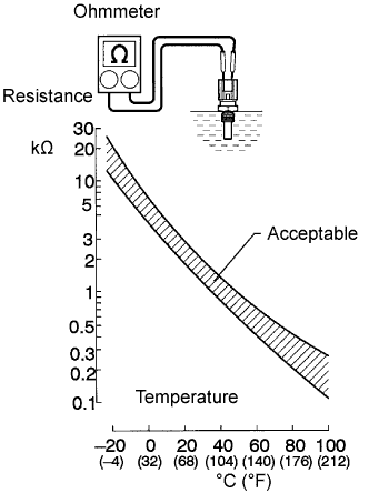
7.INSPECT ENGINE COOLANT TEMPERATURE SENSOR


    A081700E11
  1. Remove the engine coolant temperature sensor.

  1. Measure the resistance according to the value(s) in the table below.

    Standard resistance:
    Tester Connection
    Condition
    Specified Condition
    1 - 2
    20°C (68°F)
    2 to 3 kΩ
    1 - 2
    80°C (176°F)
    0.2 to 0.4 kΩ

    NOTICE:
    When checking the engine coolant temperature sensor in water, be careful not to allow water to contact the terminals. After checking, dry the sensor.

    HINT:
    Alternative procedure: Connect an ohmmeter to the installed engine coolant temperature sensor and read the resistance. Use an infrared thermometer to measure the engine temperature in the immediate vicinity of the sensor. Compare these values to the resistance/temperature graph. Change the engine temperature (warm up or allow to cool down) and repeat the test.

  1. Reinstall the engine coolant temperature sensor.


NG
REPLACE ENGINE COOLANT TEMPERATURE SENSOR (Click here)
OK


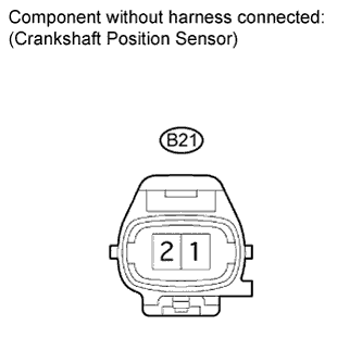
8.INSPECT CRANKSHAFT POSITION SENSOR


    A178651E03
  1. Disconnect the crankshaft position sensor connector.

  1. Measure the resistance according to the value(s) in the table below.

    Standard resistance:
    Tester Connection
    Condition
    Specified Condition
    1 - 2
    20°C (68°F)
    1850 to 2450 Ω

  1. Reconnect the crankshaft position sensor connector.


NG
REPLACE CRANKSHAFT POSITION SENSOR (Click here)
OK


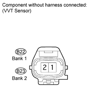
9.INSPECT VVT SENSOR


    A178651E04
  1. Disconnect the VVT sensor connectors.

  1. Measure the resistance according to the value(s) in the table below.

    Standard resistance:
    Tester Connection
    Condition
    Specified Condition
    1 - 2
    20°C (68°F)
    950 to 1250 Ω

  1. Reconnect the VVT sensor connector.


NG
REPLACE VVT SENSOR (Click here)
OK


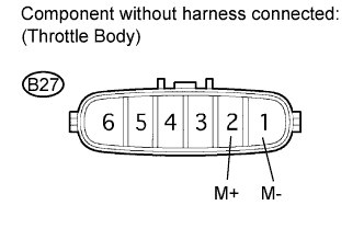
10.INSPECT THROTTLE CONTROL MOTOR


    A059778E65
  1. Disconnect the throttle control motor connector.

  1. Measure the resistance according to the value(s) in the table below.

    Standard resistance:
    Tester Connection
    Condition
    Specified Condition
    1 - 2
    20°C (68°F)
    0.3 to 100 Ω


NG
REPLACE THROTTLE BODY ASSEMBLY (Click here)
OK


11.INSPECT THROTTLE POSITION SENSOR
  1. Connect the Techstream to the DLC3.

  1. Turn the power switch on (IG) and turn Techstream on.

  1. Enter the following menus: Powertrain / Engine and ECT / Data List / Throttle Sens Open Pos #1 and Throttle Sens Open Pos #2.

  1. Check the values displayed on the Techstream.

    Standard voltage:

    Item
    Condition
    Specified Condition
    Throttle Sens Open Pos #1
    Throttle fully closed
    2.15 to 2.35 V
    Throttle fully open
    4.5 to 5.0 V
    Throttle Sens Open Pos #2
    Throttle fully closed
    0.66 to 0.76 V
    Throttle fully open
    3.8 to 4.2 V


NG
REPLACE THROTTLE BODY ASSEMBLY (Click here)
OK

REPLACE HYBRID VEHICLE CONTROL ECU (Click here)