 |
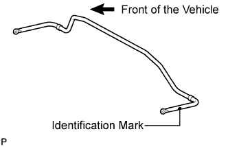
Temporarily install the rear stabilizer bar with the identification mark positioned on the left side of the vehicle.
REAR STABILIZER BAR > INSTALLATION |
| 1. TEMPORARILY INSTALL REAR STABILIZER BAR |
|
Temporarily install the rear stabilizer bar with the identification mark positioned on the left side of the vehicle.
| 2. TEMPORARILY INSTALL REAR STABILIZER BAR BRACKET LH (for Front Side) |
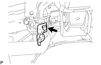 |
Temporarily install the rear stabilizer bar bracket LH (front side) with the bolt.
| 3. TEMPORARILY INSTALL REAR STABILIZER BAR BRACKET RH (for Front Side) |
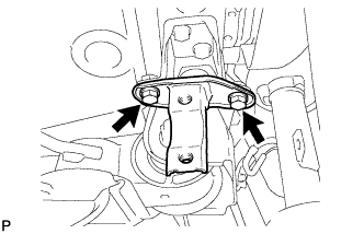 |
Temporarily install the rear stabilizer bar bracket RH (front side) with the 2 bolts.
| 4. INSTALL REAR STABILIZER BUSHING (for LH Side) |
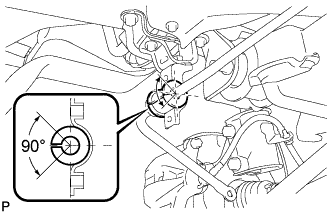 |
Install the rear stabilizer bushing (LH side) to the rear stabilizer bar.
| 5. INSTALL REAR STABILIZER BUSHING (for RH Side) |
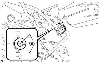 |
Install the rear stabilizer bushing (RH side) to the rear stabilizer bar.
| 6. INSTALL REAR STABILIZER BAR BRACKET LH (for Rear Side) |
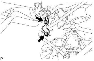 |
Install the rear stabilizer bar bracket LH (rear side) with the 2 bolts.
| 7. INSTALL REAR STABILIZER BAR BRACKET RH (for Rear Side) |
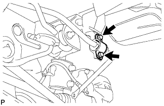 |
Install the rear stabilizer bar bracket RH (rear side) with the 2 bolts.
| 8. FULLY TIGHTEN REAR STABILIZER BAR BRACKET LH (for Front Side) |
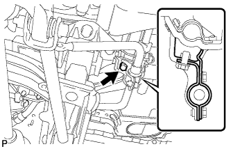 |
Fully tighten the bolt.
| 9. FULLY TIGHTEN REAR STABILIZER BAR BRACKET RH (for Front Side) |
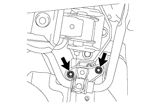 |
Fully tighten the 2 bolts.
| 10. INSTALL REAR STABILIZER LINK ASSEMBLY LH |
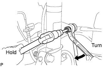 |
Install the rear stabilizer link assembly LH to the rear shock absorber with coil spring LH with the nut.
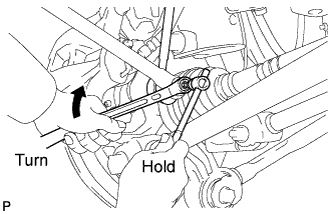 |
Install the rear stabilizer link assembly LH to the rear stabilizer bar with the nut.
| 11. INSTALL REAR STABILIZER LINK ASSEMBLY RH |
| 12. INSTALL TAIL EXHAUST PIPE ASSEMBLY |
Inspect the compression spring.
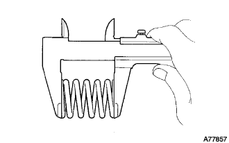 |
Using a vernier caliper, measure the free length of the compression spring.
| Minimum | 40.5 mm (1.594 in.) |
Fully insert a new gasket to the center exhaust pipe assembly.
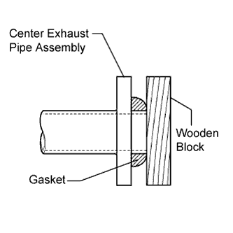 |
Using a plastic hammer and wooden block, tap in the new gasket until its surface is flush with the center exhaust pipe assembly
Connect the tail exhaust pipe assembly to the exhaust pipe support.
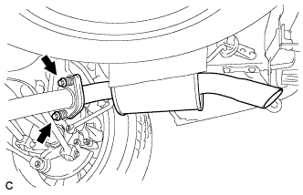 |
Tighten the 2 bolts and 2 compression springs.
| 13. INSPECT FOR EXHAUST GAS LEAK |
| 14. INSTALL REAR WHEELS |
| 15. INSTALL SPARE TIRE |
| 16. INSTALL DECK TRIM SERVICE HOLE COVER |
| 17. INSTALL REAR MAT |
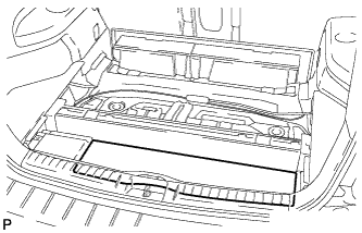 |
Install the rear mat.
| 18. INSTALL TONNEAU COVER ASSEMBLY (w/ Tonneau Cover) |
Install the tonneau cover assembly.
| 19. INSTALL NO. 2 DECK BOARD SUB-ASSEMBLY (w/ Tonneau Cover) |
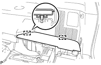 |
Engage the 2 guides and install the No. 2 deck board sub-assembly.
| 20. INSTALL NO. 3 DECK BOARD SUB-ASSEMBLY (w/ Tonneau Cover) |
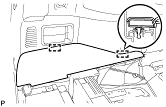 |
Engage the 2 guides and install the No. 3 deck board sub-assembly.
| 21. INSTALL DECK BOARD ASSEMBLY |
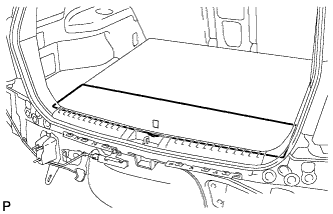 |
Install the deck board assembly.