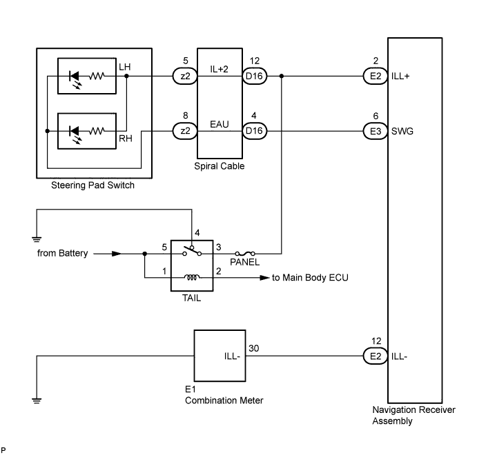
NAVIGATION SYSTEM > Illumination Circuit |
| 1.CHECK ILLUMINATION |
Check if the illumination for the navigation receiver assembly, steering pad switch, glove box or others (hazard switch, transmission control switch, etc.) comes on when the light control switch is turned to the HEAD or TAIL position.
| Result | Proceed to |
| Illumination comes on for all components except steering pad switch. | A |
| Illumination comes on for all components except navigation receiver assembly. | B |
| No illumination comes on (navigation receiver assembly, hazard switch, glove box, etc.). | C |
| Illumination comes on only for steering pad switch and glove box. | D |
|
| ||||
|
| ||||
|
| ||||
| A | |
 |
| 2.CHECK HARNESS AND CONNECTOR (BATTERY - SPIRAL CABLE) |
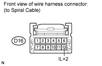 |
Disconnect spiral cable connector D16.
Measure the voltage according to the value(s) in the table below.
| Tester Connection | Condition | Specified Condition |
| D16-12 (IL+2) - Body ground | Light control switch in TAIL or HEAD | 11 to 14 V |
|
| ||||
| OK | |
|
| 3.INSPECT SPIRAL CABLE |
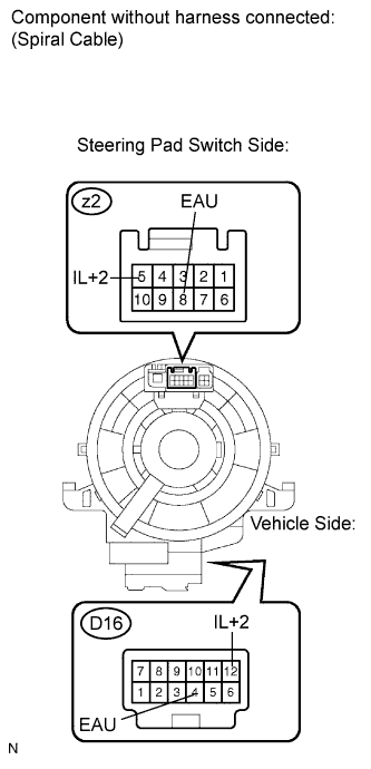 |
Disconnect the steering pad switch and spiral cable connectors.
Measure the resistance according to the value(s) in the table below.
| Tester Connection | Condition | Specified Condition |
| z2-8 (EAU) - D16-4 (EAU) | Center | Below 1 Ω |
| 2.5 rotations to the left | ||
| 2.5 rotations to the right | ||
| z2-5 (IL+2) - D16-12 (IL+2) | Center | Below 1 Ω |
| 2.5 rotations to the left | ||
| 2.5 rotations to the right |
|
| ||||
| OK | |
|
| 4.CHECK HARNESS AND CONNECTOR (SPIRAL CABLE - NAVIGATION RECEIVER ASSEMBLY) |
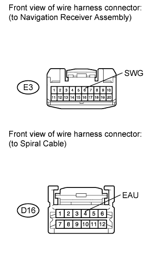 |
Disconnect the navigation receiver assembly and spiral cable connectors.
Measure the resistance according to the value(s) in the table below.
| Tester Connection | Condition | Specified Condition |
| E3-6 (SWG) - D16-4 (EAU) | Always | Below 1 Ω |
| E3-6 (SWG) - Body ground | Always | 10 kΩ or higher |
|
| ||||
| OK | |
|
| 5.INSPECT STEERING PAD SWITCH ASSEMBLY |
Disconnect steering pad switch assembly connector z2.
Connect the positive (+) lead to terminal IL+2 and the negative (-) lead to terminal EAU of the steering pad switch connector.
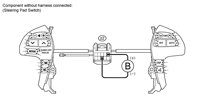
Check if the illumination for the steering pad switch comes on.
|
| ||||
| OK | ||
 | ||
| ||
| 6.CHECK HARNESS AND CONNECTOR (BATTERY - NAVIGATION RECEIVER ASSEMBLY) |
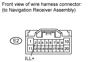 |
Disconnect navigation receiver assembly connector E2.
Measure the voltage according to the value(s) in the table below.
| Tester Connection | Condition | Specified Condition |
| E2-2 (ILL+) - Body ground | Light control switch in TAIL or HEAD | 11 to 14 V |
|
| ||||
| OK | |
|
| 7.CHECK HARNESS AND CONNECTOR (NAVIGATION RECEIVER ASSEMBLY - COMBINATION METER) |
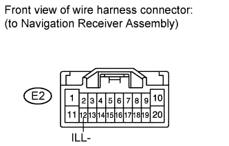 |
Disconnect navigation receiver assembly connector E2.
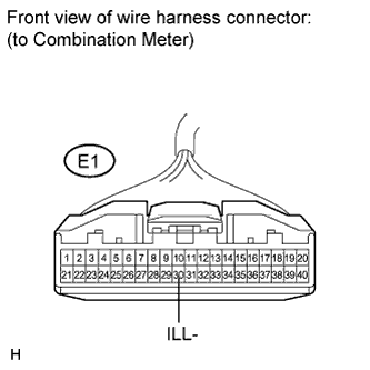 |
Disconnect combination meter connector E1.
Measure the resistance according to the value(s) in the table below.
| Tester Connection | Condition | Specified Condition |
| E2-12 (ILL-) - E1-30 (ILL-) | Always | Below 1 Ω |
| E2-12 (ILL-) - Body ground | Always | 10 kΩ or higher |
|
| ||||
| OK | ||
| ||
| ||

