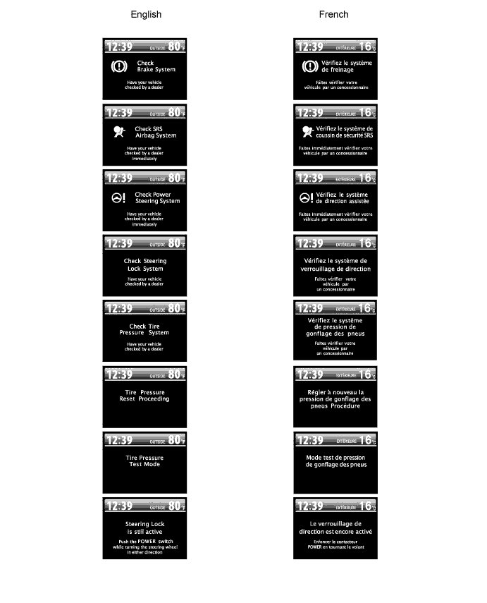
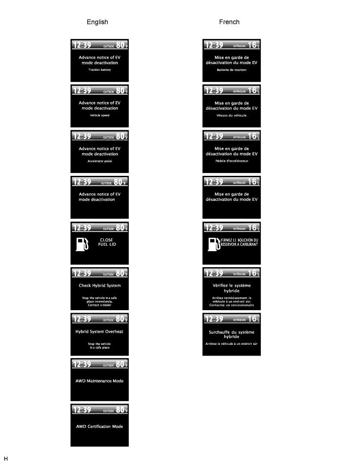
Warning/Indicator:
Item
| Detail
|
Turn
| Receives a turn signal from the turn signal flasher. (Direct Line)
|
Beam
| Receives a beam indicator light signal from the main body ECU. (CAN (CAN No. 1 Bus))
|
Charge
| Receives a charge indicator light signal from the hybrid vehicle control ECU. (CAN No. 1 Bus)
|
MIL (Check engine)
| Receives a check engine warning light signal from the hybrid vehicle control ECU. (Direct Line)
|
Door
| Open door warning light comes on receiving a door condition signal from the main body ECU. (CAN (CAN No. 1 Bus))
|
Driver side seat belt
| Receives a driver side seat belt signal from the center airbag sensor assembly. (CAN (CAN No. 1 Bus))
|
Front passenger side seat belt
| Receives a passenger side seat belt signal from the center airbag sensor assembly (CAN (CAN No. 1 Bus)) and transmits a passenger side seat belt condition signal to the hazard warning switch. (Direct Line)
|
Head (*1)/Tail (*2)
| Receives a head/tail indicator light signal from the main body ECU. (CAN (CAN No. 1 Bus))
|
Front fog
| Receives a front fog indicator light signal from the main body ECU. (CAN (CAN No. 1 Bus))
|
Hybrid transaxle shift
| Receives an hybrid transaxle shift condition signal from the hybrid vehicle control ECU. (CAN (CAN No. 1 Bus))
|
Fuel
| Receives a fuel signal from the fuel sender gauge. (Direct Line)
|
ABS
| Receives an ABS signal from the skid control ECU. (CAN (CAN No. 1 Bus))
|
Slip
| Receives a slip signal from the skid control ECU. (CAN (CAN No. 1 Bus))
|
Brake
| Receives a brake signal from the skid control ECU. (CAN (CAN No. 1 Bus))
|
Cruise
| Receives a cruise signal from the hybrid vehicle control ECU. (CAN (CAN No. 1 Bus))
|
SRS
| Receives an SRS signal from the center airbag sensor assembly. (CAN (CAN No. 1 Bus))
|
Ready
| Receives a ready signal from the hybrid vehicle control ECU. (CAN (CAN No. 1 Bus))
|
Electrically controlled brake
| Receives an electrically controlled brake signal from the skid control ECU. (CAN (CAN No. 1 Bus))
|
EPS
| Receives an EPS signal from the power steering ECU. (CAN (CAN No. 1 Bus))
|
Washer (in the multi-information display)
| Receives a washer signal from the washer level warning switch. (Direct Line)
|
Tire pressure
| Receives a tire pressure signal from the tire pressure warning ECU. (CAN (CAN MS Bus))
|
Oil pressure (in the multi-information display)
| Receives an oil pressure signal from the hybrid vehicle control ECU. (CAN (CAN No. 1 Bus))
|
Hybrid system
| Receives a hybrid system signal from the hybrid vehicle control ECU. (CAN (CAN No. 1 Bus))
|
ECON
| Receives an ECON indicator signal from the hybrid vehicle control ECU. (CAN (CAN No. 1 Bus))
|
EV indicator
| Receives an EV indicator signal from the hybrid vehicle control ECU. (CAN (CAN No. 1 Bus))
|
Maintenance (in the multi-information display)
| Illuminates or blinks the oil maintenance reminder based on an odometer signal.
|
Master caution indicator light
| Master caution indicator light comes on when the warning display appears or the oil maintenance reminder resetting procedure has finished.
|
Item
| Detail
|
Cruise information display
| - Average fuel consumption after refueling
- Current fuel consumption
- Possible running distance
- Total cruising distance
- Total average fuel consumption
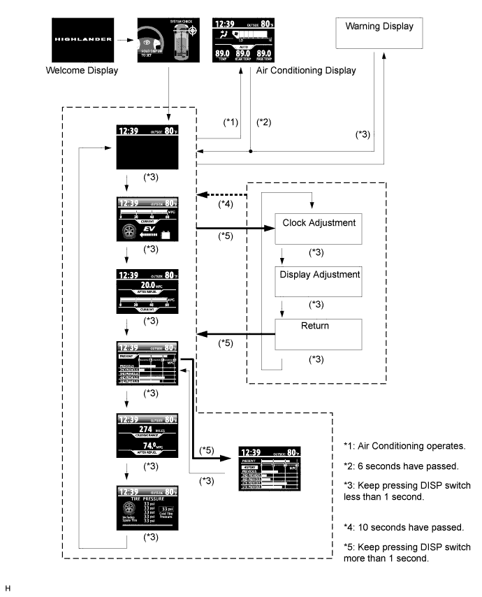
| Five types of information (average fuel consumption after refueling, current fuel consumption, possible running distance, total cruising distance since reset, and total average fuel consumption since reset) can be displayed.
|
Warning display
| - Door warning
- Each system warning
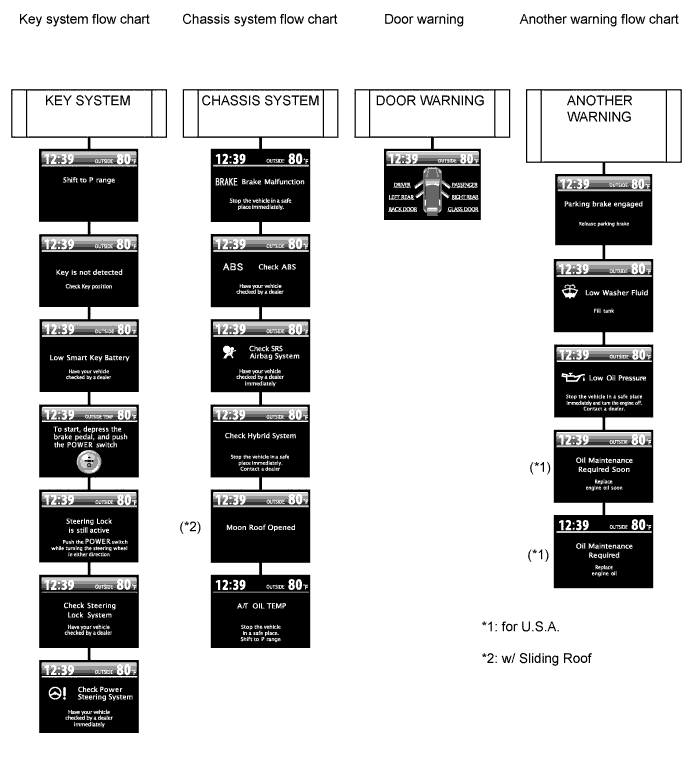
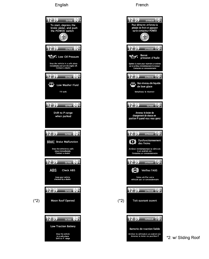
| Interrupts the multi-information display immediately when a warning occurs.
|
Air conditioning display
| Interrupts the multi-information display immediately when air conditioning is operated.
|
Adjustment display
| Three types of information (clock adjustment, illuminance adjustment, and tire pressure information) can be displayed.
|
Clock
| Displays the time.
|
Outside temperature display
| Displays the outside temperature.
|
Energy flow display
| Energy monitor indicates the energy transmission direction for checking the current drive method (engine, motor or both), the power generation status by the engine and status of regenerative energy use.
|
DTC (Diagnostic Trouble Code) display
| Displays DTCs pertaining to the electrically controlled brake function.
|