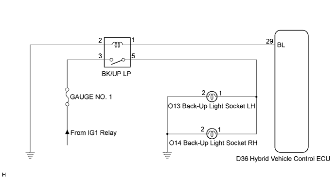
LIGHTING SYSTEM > Back-up Light Circuit |
| 1.INSPECT FUSE (GAUGE NO. 1) |
Remove the GAUGE NO. 1 fuse from the engine room relay block.
Measure the resistance according to the value(s) in the table below.
| Tester Connection | Condition | Specified Condition |
| GAUGE NO. 1 fuse | Always | Below 1 Ω |
|
| ||||
| OK | |
 |
| 2.INSPECT BACK-UP LIGHT RELAY |
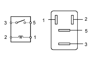 |
Remove the back-up light relay from the engine room relay block.
Measure the resistance according to the value(s) in the table below.
| Tester Connection | Specified Condition |
| 3 - 5 | 10 kΩ or higher (When battery voltage is not applied to terminals 1 and 2) |
| Below 1 Ω (When battery voltage is applied to terminals 1 and 2) |
|
| ||||
| OK | |
|
| 3.CHECK HARNESS AND CONNECTOR (RELAY - HYBRID VEHICLE CONTROL ECU AND BODY GROUND) |
Disconnect the D36 hybrid vehicle control ECU connector.
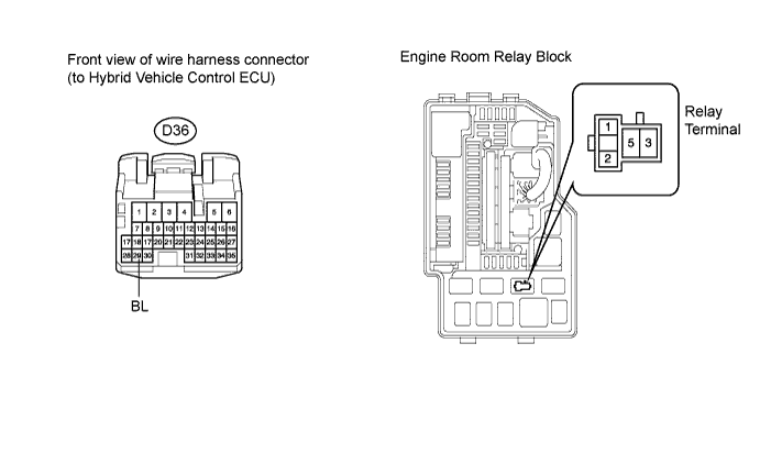
Remove the back-up relay from the engine room relay block.
Measure the resistance according to the value(s) in the table below.
| Tester connection | Condition | Specified value |
| D36-29 (BL) - Relay terminal 1 | Always | Below 1 Ω |
| Relay terminal 2 - Body ground | Always | Below 1 Ω |
|
| ||||
| OK | |
|
| 4.INSPECT HYBRID VEHICLE CONTROL ECU |
Reconnect the hybrid vehicle control ECU connector.
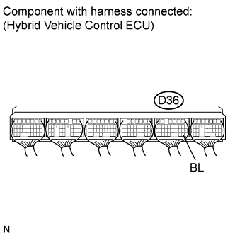 |
Measure the voltage according to the value(s) in the table below.
| Tester connection | Condition | Specified value |
| D36-29 (BL) - Body ground | Shift lever in R position | 10 to 14 V |
| Shift lever not in R position | Below 1 V |
|
| ||||
| OK | |
|
| 5.CHECK HARNESS AND CONNECTOR (BATTERY - RELAY) |
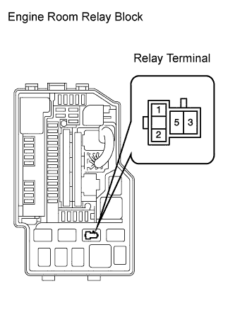 |
Measure the voltage according to the value(s) in the table below.
| Tester connection | Condition | Specified value |
| Relay terminal 3 - Body ground | Power switch on (IG) | 10 to 14 V |
| Relay terminal 3 - Body ground | Power switch off | Below 1 V |
|
| ||||
| OK | ||
 | ||
| ||
