Home › BRAKE › BRAKE CONTROL › BRAKE ACTUATOR

BRAKE ACTUATOR > ON-VEHICLE INSPECTION

for Preparation Click here


1. CHECK BRAKE ACTUATOR OPERATION
  1. Prepare for operation check.

    1. Move the shift lever to the P position. Apply the parking brake and connect the Techstream to the DLC3.

    2. Turn the power switch on (IG).

    3. Turn on the Techstream.

    4. Enter the following menus: Chassis / ABS/VSC/TRAC / Data List / Master Cylinder Sensor, Master Cylinder Sensor 2, FR W/C Sensor, FL W/C Sensor, RR W/C Sensor, and RL W/C Sensor.

  1. Check the FR system solenoid (SLA##, SLR##, Electronically Controlled Brake System Solenoid (SMC1), Electronically Controlled Brake System Solenoid (SMC2)).

    1. Select Active Test: Electronically Controlled Brake System Solenoid (SLAFR) valve close. Check the output voltage.

      NOTICE:
      Do not depress the brake pedal.

      HINT:
      It takes approximately 35 seconds to complete the check.


      Standard voltage:

      Sensor
      10 to 20 sec. after check start (V)
      35 sec. or more after check start (V)
      Master Cylinder Sensor
      0.3 to 0.7
      0.3 to 0.7
      Master Cylinder Sensor 2
      0.3 to 0.7
      0.3 to 0.7
      FR W/C Sensor
      2.5 to 4.5
      0.3 to 0.7
      FL W/C Sensor
      0.3 to 0.7
      0.3 to 0.7
      RR W/C Sensor
      0.3 to 0.7
      0.3 to 0.7
      RL W/C Sensor
      0.3 to 0.7
      0.3 to 0.7

      If not as specified, troubleshoot the brake system (Click here).

  1. Check the FL system solenoid (SLA##, SLR##, Electronically Controlled Brake System Solenoid (SMC1), Electronically Controlled Brake System Solenoid (SMC2)).

    1. Select Active Test: Electronically Controlled Brake System Solenoid (SLAFL) valve close. Check the output voltage.

      NOTICE:
      Do not depress the brake pedal.

      HINT:
      It takes approximately 35 seconds to complete the check.


      Standard voltage:

      Sensor
      10 to 20 sec. after check start (V)
      35 sec. or more after check start (V)
      Master Cylinder Sensor
      0.3 to 0.7
      0.3 to 0.7
      Master Cylinder Sensor 2
      0.3 to 0.7
      0.3 to 0.7
      FR W/C Sensor
      0.3 to 0.7
      0.3 to 0.7
      FL W/C Sensor
      2.5 to 4.5
      0.3 to 0.7
      RR W/C Sensor
      0.3 to 0.7
      0.3 to 0.7
      RL W/C Sensor
      0.3 to 0.7
      0.3 to 0.7

      If not as specified, troubleshoot the brake system (Click here).

  1. Check the RR system solenoid (SLA##, SLR##, Electronically Controlled Brake System Solenoid (SMC1), Electronically Controlled Brake System Solenoid (SMC2)).

    1. Select Active Test: Electronically Controlled Brake System Solenoid (SLARR) valve close. Check the output voltage.

      NOTICE:
      Do not depress the brake pedal.

      HINT:
      It takes approximately 35 seconds to complete the check.


      Standard voltage:

      Sensor
      10 to 20 sec. after check start (V)
      35 sec. or more after check start (V)
      Master Cylinder Sensor
      0.3 to 0.7
      0.3 to 0.7
      Master Cylinder Sensor 2
      0.3 to 0.7
      0.3 to 0.7
      FR W/C Sensor
      0.3 to 0.7
      0.3 to 0.7
      FL W/C Sensor
      0.3 to 0.7
      0.3 to 0.7
      RR W/C Sensor
      2.5 to 4.7
      0.3 to 0.7
      RL W/C Sensor
      0.3 to 0.7
      0.3 to 0.7

      If not as specified, troubleshoot the brake system (Click here).

  1. Check the RL system solenoid (SLA##, SLR##, Electronically Controlled Brake System Solenoid (SMC1), Electronically Controlled Brake System Solenoid (SMC2)).

    1. Select Active Test: Electronically Controlled Brake System Solenoid (SLARL) valve close. / Check the output voltage.

      NOTICE:
      Do not depress the brake pedal.

      HINT:
      It takes approximately 35 seconds to complete the check.


      Standard voltage:

      Sensor
      10 to 20 sec. after check start (V)
      35 sec. or more after check start (V)
      Master Cylinder Sensor
      0.3 to 0.7
      0.3 to 0.7
      Master Cylinder Sensor 2
      0.3 to 0.7
      0.3 to 0.7
      FR W/C Sensor
      0.3 to 0.7
      0.3 to 0.7
      FL W/C Sensor
      0.3 to 0.7
      0.3 to 0.7
      RR W/C Sensor
      0.3 to 0.7
      0.3 to 0.7
      RL W/C Sensor
      2.5 to 4.7
      0.3 to 0.7

      If not as specified, troubleshoot the brake system (Click here).

  1. Check the changeover solenoid valves (SMC1, SMC2).

    1. Enter the following menus: Chassis / ABS/VSC/TRAC / Electronically Controlled Brake Utility / Electronically Controlled Brake Invalid / enter Electronically Controlled Brake system Invalid to prohibit the brake control.

    2. Check that the brake control warning light comes on.

    3. Enter the following menus: Chassis / ABS/VSC/TRAC / Data List / Master Cylinder Sensor, Master Cylinder Sensor 2, FR W/C Sensor and FL W/C Sensor.

    4. Check the output voltage by depressing the brake pedal.

      Standard voltage:
      Difference in output voltage between "Master Cylinder Sensor" and "FR W/C Sensor" is less than 0.4 V.
      Difference in output voltage between "Master Cylinder Sensor 2" and "FL W/C Sensor" is less than 0.4 V.

    5. Enter the following menus: Chassis / ABS/VSC/TRAC / Electronically Controlled Brake Utility / Electronically Controlled Brake Invalid / and cancel brake control prohibition (Electronically Controlled Brake Invalid).


2. CHECK PRESSURE SENSOR OPERATION
  1. Check the battery voltage.

    Standard voltage:
    11 to 14 V (with the engine stopped)


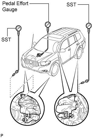
  1. Connect a hydro LSPV gauge (SST) and pedal effort gauge.


      C171440E02
    1. Install a hydro LSPV gauge (SST) and brake pedal effort gauge.

      SST
      09709-29018  

    2. Bleed air from the LSPV gauge (SST).

    3. Move the shift lever to the P position. Connect the Techstream to the DLC3 with the parking brake applied.

    4. Turn the power switch on (IG).

    5. Clear the DTCs (Click here).

  1. Check the wheel cylinder pressure sensor and master pressure sensor.

    1. Turn on the Techstream.

    2. Enter the following menus: Chassis / ABS/VSC/TRAC / Data List / Master Cylinder Sensor, Master Cylinder Sensor 2, FR W/C Sensor, FL W/C Sensor, RR W/C Sensor, and RL W/C Sensor.

    3. Check the brake pedal effort gauge and the LSPV gauge (SST) readings, and the output pressure voltage.

      Standard voltage:

      Brake Effort N (kgf, lbf)
      Master Cylinder Sensor (V)
      Master Cylinder Sensor 2 (V)
      200 (20.4, 45.0)
      0.90 to 1.30
      0.90 to 1.30
      500 (51, 112.4)
      2.10 to 2.50
      2.10 to 2.50


      Standard voltage:

      Brake Effort N (kgf, lbf)
      Front Right Wheel Hydraulic Pressure MPa (kgf/cm2, psi)
      FR W/C Sensor (V)
      50 (5.1, 11.2)
      2.4 (24.5, 348)
      0.80 to 1.20
      100 (10.2, 22.4)
      5.4 (54.1, 783)
      1.40 to 1.80
      150 (15.3, 34.0)
      6.5 (66.3, 943)
      1.60 to 2.00
      200 (20.4, 45.0)
      7.1 (72.4, 1030)
      1.75 to 2.15


      Standard voltage:

      Brake Effort N (kgf, lbf)
      Front Left Wheel Hydraulic Pressure MPa (kgf/cm2, psi)
      FL W/C Sensor (V)
      50 (5.1, 11.2)
      2.4 (24.5, 348)
      0.80 to 1.20
      100 (10.2, 22.4)
      5.4 (54.1, 783)
      1.40 to 1.80
      150 (15.3, 34.0)
      6.5 (66.3, 943)
      1.60 to 2.00
      200 (20.4, 45.0)
      7.1 (72.4, 1030)
      1.75 to 2.15


      Standard voltage:

      Brake Effort N (kgf, lbf)
      Rear Right Wheel Hydraulic Pressure MPa (kgf/cm2, psi)
      RR W/C Sensor (V)
      50 (5.1, 11.2)
      2.4 (24.5, 348)
      0.80 to 1.20
      100 (10.2, 22.4)
      5.0 (51.0, 725)
      1.30 to 1.70
      150 (15.3, 34.0)
      5.0 (51.0, 725)
      1.30 to 1.70
      200 (20.4, 45.0)
      5.0 (51.0, 725)
      1.30 to 1.70


      Standard voltage:

      Brake Effort N (kgf, lbf)
      Rear Left Wheel Hydraulic Pressure MPa (kgf/cm2, psi)
      RL W/C Sensor (V)
      50 (5.1, 11.2)
      2.4 (24.5, 348)
      0.80 to 1.20
      100 (10.2, 22.4)
      5.0 (51.0, 725)
      1.30 to 1.70
      150 (15.3, 34.0)
      5.0 (51.0, 725)
      1.30 to 1.70
      200 (20.4, 45.0)
      5.0 (51.0, 725)
      1.30 to 1.70

      If not as specified, troubleshoot the brake system (Click here).

  1. Check the accumulator sensor.

    1. Move the shift lever to the P position. Apply the parking brake and connect the Techstream to the DLC3.

    2. Turn the power switch on (IG).

    3. Turn on the Techstream.

    4. Enter the following menus: Chassis / ABS/VSC/TRAC / Data List / the Accumulator Sensor.

    5. Temporarily operate the pump motor by depressing the brake pedal 4 or 5 times.

    6. After confirming that the pump motor stops, check the pressure output voltage.

      Standard voltage:
      2.6 to 3.8 V

      If not as specified, troubleshoot the brake system (Click here).