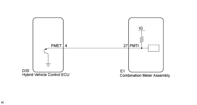
METER / GAUGE SYSTEM > Power Meter Gauge Malfunction |
| 1.PERFORM ACTIVE TEST USING TECHSTREAM (POWER METER OPERATION) |
Connect Techstream to the DLC3.
Power switch on (READY).
Turn the tester ON.
Enter following menus: Body Electrical / Combination Meter / Active Test.
Check the operation by referring to the table below.
| Tester Display | Test Part | Control Range | Diagnostic Note |
| Power Meter Operation | Power Meter | Power meter gauge indicates 0, 50, 100, 150, 200 (kW) | Confirm that the vehicle is stopped, engine idling. |
|
| ||||
| OK | |
 |
| 2.CHECK HARNESS AND CONNECTOR (COMBINATION METER - HYBRID VEHICLE CONTROL ECU) |
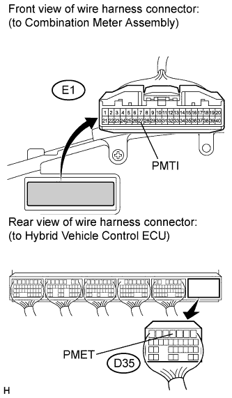 |
Disconnect the E1 and D35 connectors.
Measure the resistance according to the value(s) in the table below.
| Tester Connection | Condition | Specified Condition |
| E1-27 (PMTI) - D35-4 (PMET) | Always | Below 1 Ω |
| E1-27 (PMTI) - Body ground | Always | 10 kΩ or higher |
|
| ||||
| OK | |
|
| 3.INSPECT COMBINATION METER ASSEMBLY (OUTPUT VOLTAGE) |
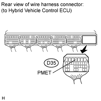 |
Reconnect the E1 connector.
Measure the voltage according to the value(s) in the table below.
| Tester Connection | Condition | Specified Condition |
| D35-4 (PMET) - Body ground | Power switch on (READY) | 11 to 14 V |
|
| ||||
| OK | |
|
| 4.INSPECT HYBRID VEHICLE CONTROL ECU (WAVEFORM) |
Check the signal waveform.
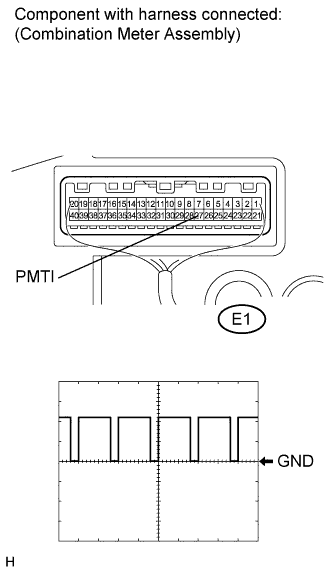 |
Remove the combination meter assembly with connector still connected.
Connect an oscilloscope to the terminals E1-27 (PMTI) and body ground.
Reconnect the D35 connector.
Depress the brake pedal, and turn the power switch on (READY).
Check the signal waveform according to the condition(s) in the table below.
| Item | Condition |
| Tool setting | 1 V/DIV., 2 μs/DIV. |
| Vehicle condition | Power switch on (READY). |
|
| ||||
| OK | ||
 | ||
| ||
