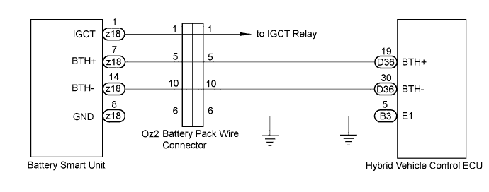
DTC U029A-123 Lost Communication with Hybrid Battery Pack Sensor Module |
| DTC No. | DTC Detection Condition | Trouble Area |
| U029A-123 | Problem in serial communication between the battery smart unit and hybrid vehicle control ECU (1 trip detection) |
|
| Related DTCs | U029A-123: Battery smart unit communication malfunction |
| Required sensors/components | Main: Battery smart unit Sub: Communication line |
| Frequency of operation | Continuous |
| Duration | TOYOTA's intellectual property |
| MIL operation | 1 driving cycle |
| Sequence of operation | None |
| The monitor will run whenever the DTCs listed are not present | TOYOTA's intellectual property |
| Receive an error in communication between the battery smart unit and the hybrid vehicle control ECU | Error |
| Battery smart unit | DTC U029A-123 is not detected |
| 1.INSPECT HYBRID VEHICLE CONTROL ECU |
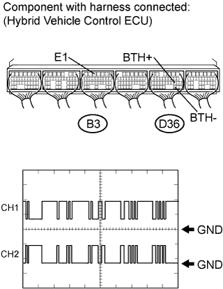 |
Using an oscilloscope, measure the waveform according to the condition in the table below (Click here).
| Item | Contents |
| Terminal | CH1: D36-19 (BTH+) - B3-5 (E1) CH2: D36-30 (BTH-) - B3-5 (E1) |
| Equipment Setting | 2 V/DIV, 500 μs/DIV |
| Switch Condition | Power switch on (IG) |
|
| ||||
| OK | ||
 | ||
| ||
| 2.CHECK HARNESS AND CONNECTOR (HYBRID VEHICLE CONTROL ECU - BATTERY PACK WIRE) |
Disconnect the D36 connector from the hybrid vehicle control ECU.
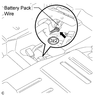 |
Disconnect the Oz2 connector shown in the illustration (Click here).
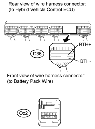 |
Measure the resistance according to the value(s) in the table below.
| Tester Connection | Switch Condition | Specified Condition |
| D36-19 (BTH+) - Oz2-5 | Power switch off | Below 1 Ω |
| D36-30 (BTH-) - Oz2-10 | Power switch off | Below 1 Ω |
| Tester Connection | Switch Condition | Specified Condition |
| D36-19 (BTH+) - Body ground | Power switch off | 10 kΩ or higher |
| D36-30 (BTH-) - Body ground | Power switch off | 10 kΩ or higher |
|
| ||||
| OK | |
 |
| 3.CHECK HARNESS AND CONNECTOR (BATTERY PACK WIRE) |
Connect the D36 connector to the hybrid vehicle control ECU.
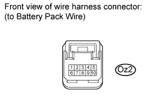 |
Measure the voltage according to the value(s) in the table below when the power switch is on (IG).
| Tester Connection | Switch Condition | Specified Condition (V) |
| Oz2-1 - Oz2-6 | Power switch on (IG) | 11 to 14 V |
|
| ||||
| OK | |
|
| 4.INSPECT BATTERY PACK WIRE |
Remove the service plug grip.
Remove the battery cover (Click here).
Disconnect the z18 connector from the battery smart unit (Click here).
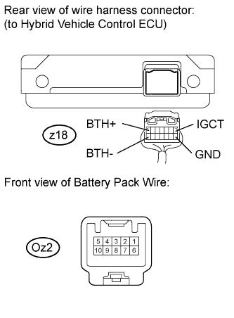 |
Measure the resistance according to the value(s) in the table below.
| Tester Connection | Switch Condition | Specified Condition |
| z18-7 (BTH+) - Oz2-5 | Power switch off | Below 1 Ω |
| z18-14 (BTH-) - Oz2-10 | Power switch off | Below 1 Ω |
| z18-1 (IGCT) - Oz2-1 | Power switch off | Below 1 Ω |
| z18-8 (GND) - Oz2-6 | Power switch off | Below 1 Ω |
| Tester Connection | Switch Condition | Specified Condition |
| z18-7 (BTH+) - Body ground | Power switch off | 10 kΩ or higher |
| z18-14 (BTH-) - Body ground | Power switch off | 10 kΩ or higher |
| z18-1 (IGCT) - Body ground | Power switch off | 10 kΩ or higher |
| z18-8 (GND) - Body ground | Power switch off | 10 kΩ or higher |
|
| ||||
| OK | ||
| ||
| ||

