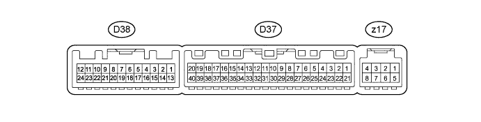
AIR CONDITIONING SYSTEM (for Manual Air Conditioning System) > TERMINALS OF ECU |
| CHECK AIR CONDITIONING AMPLIFIER |
Measure the voltage according to the value(s) in the table below..
| Tester Connection | Wiring Color | Terminal Description | Condition | Specified Condition |
| D37-1 (IG+) - D37-14 (GND) | GR - W-B | Power source (IG) | Power switch on (IG) | 11 to 14 V |
| D37-5 (TAM) - D37-14 (GND) | B - W-B | Ambient temperature sensor signal | Power switch on (IG) | 1.8 to 2.2 V |
| Ambient temperature: 25°C (77°F) | ||||
| D37-9 (PRE) - D37-13 (SG-2) | R - L | Air conditioning pressure sensor signal | Refrigerant pressure: Normal | 0.76 to 4.74 V |
| D37-9 (PRE) - D37-13 (SG-2) | R - L | Air conditioning pressure sensor signal | Refrigerant pressure: Abnormal (less than 0.196 MPa [2.0 kgf/cm2, 28 psi]) | 0.5 to 4.83 V |
| D37-9 (PRE) - D37-13 (SG-2) | R - L | Air conditioning pressure sensor signal | Refrigerant pressure: Abnormal (more than 3.14 MPa [32 kgf/cm2, 455 psi]) | 4.74 V or higher |
| D37-10 (S5-3) - D37-14 (GND) | L - W-B | Power supply for pressure sensor | Power switch on (IG) | 4.5 to 5.5 V |
| D37-11 (CANH) - D37-14 (GND) | B - W-B | Hi-level CAN bus line | Power switch on (IG) | Pulse generation (see waveform 2) |
| D37-12 (CANL) - D37-14 (GND) | W - W-B | Lo-level CAN bus line | Power switch on (IG) | Pulse generation (see waveform 3) |
| D37-13 (SG-2) - Body ground | L - Body ground | Ground for pressure sensor | Always | Below 1 V |
| D37-14 (GND) - Body ground | W-B - Body ground | Ground for main power supply | Always | Below 1 V |
| D37-21 (B) - D37-14 (GND) | LG - W-B | Power source (Back-up) | Always | 11 to 14 V |
| D37-23 (BLW) - D37-14 (GND) | R - W-B | Blower motor control signal | Power switch on (IG) | Pulse generation (see waveform 1) |
| Blower switch LO | ||||
| D37-29 (TR) - D37-35 (SG-4) | BR - LG | Room temperature sensor signal | Power switch on (IG) | 1.8 to 2.2 V |
| Vehicle interior temperature: 25°C (77°F) | ||||
| D37-35 (SG-4) - Body ground | LG - Boyd ground | Ground for room temperature sensor | Always | Below 1 V |
| D37-37 (LIN1) - D37-14 (GND) | R - W-B | LIN communication signal | Power switch on (IG) | Pulse generation |
| D37-38 (RDFG) - D37-14 (GND) | W - W-B | Rear defogger switch signal | Power switch on (IG) Rear defogger switch OFF | 11 to 14 V |
| D37-38 (RDFG) - D37-14 (GND) | W - W-B | Rear defogger switch signal | Power switch on (IG) Rear defogger switch ON | Below 1 V |
| D38-1 (RBUS) - D38-21 (RBUG) (*) | R - V | BUS IC control signal (for Rear) | Power switch on (IG) | Pulse generation |
| D38-4 (TEC) - D38-19 (SGND) (*) | B - GR | Evaporator temperature sensor signal (for Rear) | Power switch on (IG) | 1.4 to 1.8 V |
| Evaporator temperature: 15°C (59°F) | ||||
| D38-13 (RLIN) - D38-20 (GND2) (*) | B - SB | LIN communication signal (for Rear) | Power switch on (IG) | Pulse generation |
| D38-19 (SGND) - Body ground (*) | GR - Boyd ground | Ground for evaporator temperature sensor signal (for Rear) | Always | Below 1 V |
| D38-20 (GND2) - Body ground (*) | SB - Boyd ground | Ground for power supply | Always | Below 1 V |
| D38-21 (RBUG) - Body ground (*) | V - Boyd ground | Ground for BUS IC (for Rear) | Always | Below 1 V |
| D38-22 (BLWH) - D38-20 (GND2) (*) | G - SB | Blower motor control signal (for Rear) | Power switch on (IG) | Pulse generation |
| Blower switch LO | ||||
| D38-23 (RBBU) - D38-21 (RBUG) (*) | Y - V | Power supply for BUS IC (for Rear) | Power switch on (IG) | 11 to 14 V |
| D38-24 (+B2) - D38-20 (GND2) (*) | LG - SB | Power source (Back-up) (for Rear) | Always | 11 to 14 V |
| z17-2 (BUS G) - Body ground | - | Ground for BUS IC | Always | Below 1 V |
| z17-3 (BUS) - z17-2 (BUS G) | - | BUS IC control signal | power switch on (IG) | Pulse generation |
| z17-4 (B BUS) - z17-2 (BUS G) | - | Power supply for BUS IC | Power switch on (IG) | 11 to 14 V |
| z17-5 (SGA) - Body ground | - | Ground for evaporator temperature sensor | Always | Below 1 V |
| z17-6 (TEA) - z17-5 (SGA) | - | Evaporator temperature sensor signal | Power switch on (IG) | 1.4 to 1.8 V |
| Evaporator temperature: 15°C (59°F) |
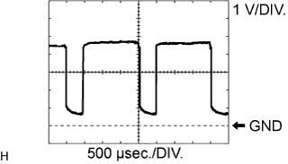 |
Using an oscilloscope, check waveform 1.
| Item | Content |
| Tester Connection | D37-23 (BLW) - D37-14 (GND) |
| Tool Setting | 1 V/DIV., 500 μsec./DIV. |
| Condition | Power switch on (IG), Blower switch LO |
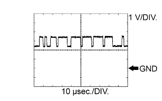 |
Using an oscilloscope, check waveform 2.
| Item | Content |
| Tester Connection | D37-11 (CANH) - D37-14 (GND) |
| Tool Setting | 1 V/DIV., 10 μsec./DIV. |
| Condition | Power switch on (IG) |
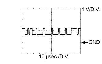 |
Using an oscilloscope, check waveform 3.
| Item | Content |
| Tester Connection | D37-12 (CANL) - D37-14 (GND) |
| Tool Setting | 1 V/DIV., 10 μsec./DIV. |
| Condition | Power switch on (IG) |
| CHECK FRONT AIR CONDITIONING CONTROL |
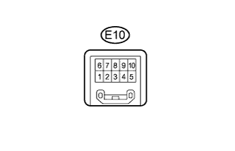
Measure the voltage according to the value(s) in the table below.
| Tester Connection | Wiring Color | Terminal Description | Condition | Specified Condition |
| E10-2 (IG+) - E10-10 (GND) | V - GR | Power source (IG) | Power switch on (IG) | 11 to 14 V |
| E10-5 (LIN1) - E10-10 (GND) | R - GR | LIN communication signal | LIN switch on (IG) | Pulse generation |
| E10-10 (GND) - Body ground | GR - Body ground | Ground for front air conditioning control | Always | Below 1 V |
| CHECK REAR AIR CONDITIONING CONTROL (for Rear Air Conditioning) |
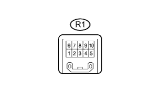
Measure the voltage according to the value(s) in the table below.
| Tester Connection | Wiring Color | Terminal Description | Condition | Specified Condition |
| R1-2 (IG+) - R1-10 (E) | V - W-B | Power source (IG) | Power switch on (IG) | 11 to 14 V |
| R1-5 (MPX-) - R1-10 (E) | B - W-B | LIN communication signal | Power switch on (IG) | Pulse generation |
| R1-10 (E) - Body ground | W-B - Body ground | Ground for rear air conditioning control | Always | Below 1 V |
| HYBRID VEHICLE CONTROL ECU |
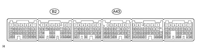
| Tester Connection | Wiring Color | Terminal Description | Condition | Specified Condition |
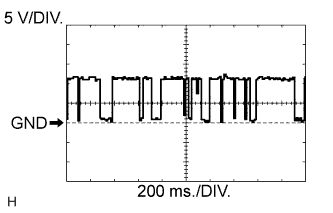
| B2-14 (CLK) - Body ground | G - Body ground | Compressor operation signal | Power switch on (IG) | Pulse generation (see waveform 1) |
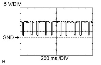
| B2-15 (ITE) - Body ground | P - Body ground | Compressor operation signal | Power switch on (IG) | Pulse generation (see waveform 2) |
| B2-16 (ETI) - Body ground | Y - Body ground | Compressor operation signal | Power switch on (IG) | Pulse generation (see waveform 3) |
| B2-18 (STB) - Body ground | B - Body ground | Compressor operation signal | Power switch on (IG) | 11 to 14 V |
| B2-18 (STB) - Body ground | B - Body ground | Compressor operation signal | Power switch on (IG) | Below 1 V |
| A43-4 (WP) - Body ground | V - Body ground | Water pump power switch: ON operation signal | Heater water pump not operated | 11 to 14 V |
| A43-4 (WP) - Body ground | V - Body ground | Water pump operation signal | The heater water pump operated | Below 1 V |
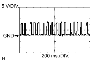 |
Using an oscilloscope, check waveform 1.
Measure the waveform between terminal CLK (B2-14) of the hybrid vehicle control ECU and body ground.
 |
Using an oscilloscope, check waveform 2.
Measure the waveform between terminal ITE (B2-15) of the hybrid vehicle control ECU and body ground.
 |
Using an oscilloscope, check waveform 3.
Measure the waveform between terminal ETI (B2-16) of the hybrid vehicle control ECU and body ground.