AIR CONDITIONING SYSTEM (for Manual Air Conditioning System) > SYSTEM DESCRIPTION |
| GENERAL |
The air conditioning system has the following features:
| MODE POSITION AND DAMPER OPERATION |
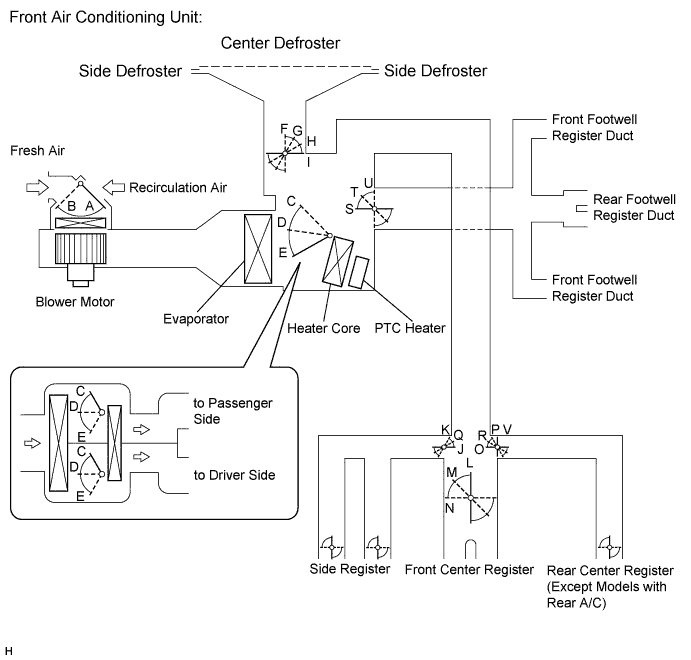
| Control Damper | Control Position | Damper Position | Operation | ||
| Air Inlet Control Damper | FRESH | A | Brings in fresh air | ||
| RECIRC | B | Recirculates internal air | |||
| Air Mix Control Damper (Left/Right Independent Control) | Driver and Front Passenger Side | MAX COOL to MAX HOT | C, D, E | Varies mixture ratio of fresh air and recirculation air in order to regulate temperature continuously from HOT to COOL | |
| Mode Control Film Damper | Driver and Front Passenger Side |  FACE | I, J, L, O, U | Air blows out of center registers and side registers. | |
 BI-LEVEL | I, M, Q, R, T | Air mainly blows out of center registers, side registers, and footwell register ducts. | |||
 FOOT | H, K, N, P, S | Air mainly blows out of front and rear footwell register ducts. In addition, air blows out slightly from front and side defrosters, and side registers. | |||
 FOOT/DEF | G, K, N, P, S | Air mainly blows out of front and side defrosters to defrost windshield. Air also blows out from front and rear footwell register ducts, and side registers. | |||
 DEF | F, K, N, U, V | Air blows out of front and side defrosters and side registers to defrost windshield. | |||
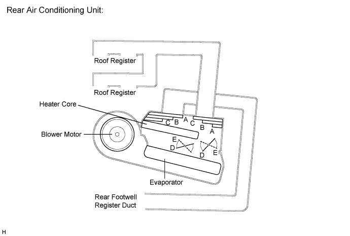
| Control Damper | Control Position | Damper Position | Operation | |
| Air Mix Control Damper | MAX COOL to MAX HOT | D, E | Varies mixture ratio of fresh air and recirculation air in order to regulate temperature continuously from HOT to COOL | |
| Mode Control Film Damper | FACE | A | Air blows out of roof face ducts. | |
BI-LEVEL | B | Air blows out of roof face ducts and rear foot ducts. | ||
FOOT | C | Air blows out of foot face ducts. | ||
| AIR OUTLET AND AIRFLOW VOLUME |
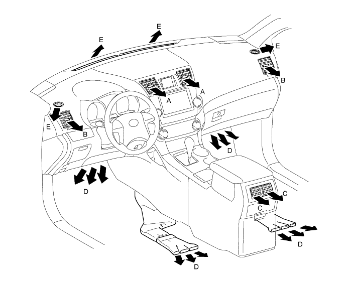
| Air Outlet Mode | Air Outlet Position Symbol | |||||
| A | B | C | D | E | ||
| Center Face | Side Face | Foot | Footwell | Defroster | ||
| FACE |  | | - | - | - |
| BI-LEVEL |  | |  | | - |
| FOOT | - |  | | | |
| FOOT/DEF | - | | | | |
| DEF | - | | - | - | |
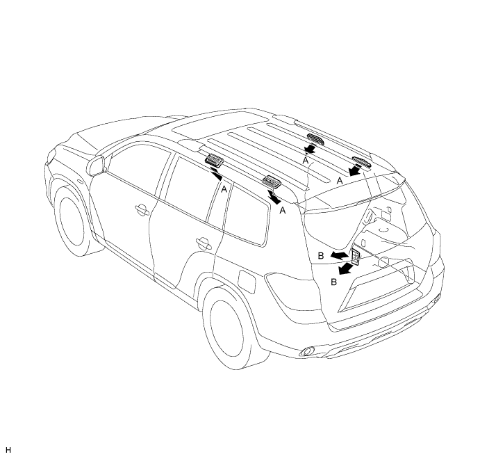
| Air Outlet Mode | Air Outlet Position Symbol | ||
| A | B | ||
| Side Face | Rear Foot | ||
| FACE | | - |
| BI-LEVEL | | |
| FOOT | - | |
| Air Conditioning Control Assembly |
For both the front and rear manual air conditioning, the blower motor speed is steplessly adjustable. Pulse type control is used.
The multi-information display is used as the manual air conditioning display.
| Air Conditioning Unit |
Front Air Conditioning Unit
The front air conditioning unit consists of the evaporator, heater core, servo motors, evaporator temperature sensor, and blower motor.
Rear Air Conditioning Unit
The rear air conditioning unit consists of the evaporator, heater core, air mix control servo motor, mode control servo motor, evaporator temperature sensor, and rear blower motor.
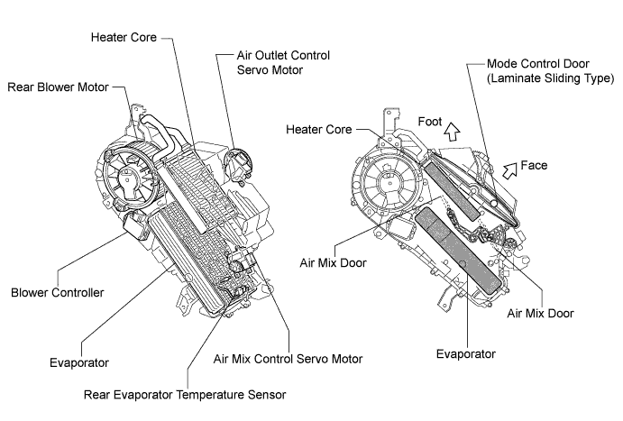
Evaporator
For the evaporator, placing the tanks at the top and the bottom and adopting a micropore tube construction have realized the following effects.
Evaporator Temperature Sensor
The evaporator temperature sensors (No. 1 cooler thermistor for the front air conditioning unit and the rear air conditioning harness for the rear air conditioning unit) each detect the temperature of the cool air immediately past the evaporator based on changes in the resistance of the built-in thermistor. The signal is used by the air conditioning amplifier.
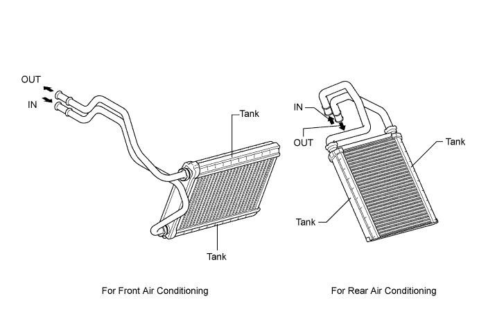
Heater Core
A compact, lightweight, and highly efficient SFA (Straight Flow Aluminum)-II type heater core is used for the front and rear air conditioning units.
Blower Motor
The front blower motor has a built-in blower controller, and the motor speed is controlled by the air conditioning amplifier using duty control.
The rear blower motor speed is controlled by the air conditioning amplifier via a blower motor controller using duty control.
Air Conditioning Harness
The BUS connectors (in the air conditioning harness) have built-in driver ICs that communicate with each servo motor, actuate the servo motor, and have a position detection function. This enables bus communication for the servo motor wire harness, lightweight construction and a reduced number of wires.
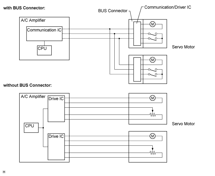
Servo Motor
Pulse pattern type servo motors are used. Each servo motor assembly consists of a printed circuit board and a servo motor. The printed circuit board has three contact points, and can transmit two signals (either ON or OFF) using the differing pulse phases. The BUS connector can detect the damper position and movement direction with this signal.
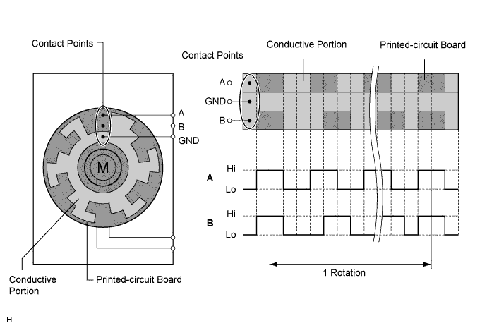
| Condenser |
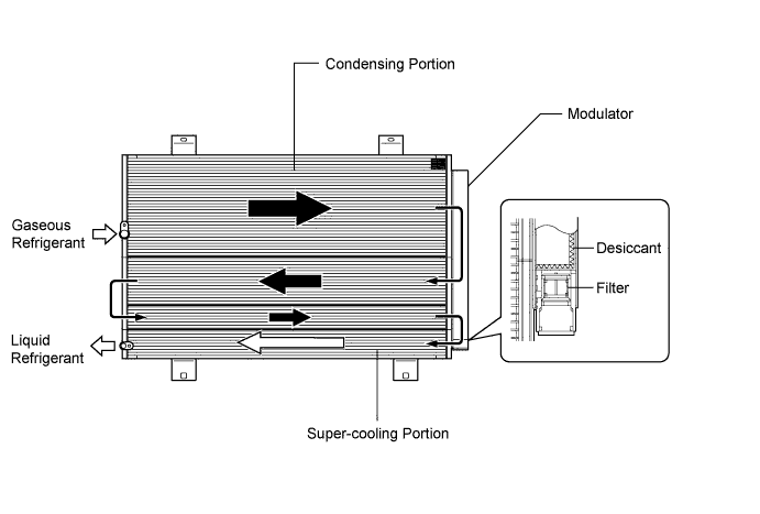
The condenser consists of two cooling portions: a condensing portion and a super-cooling portion. The condenser also has an integrated gas-liquid separator (modulator). This condenser uses the sub-cool cycle, offering excellent heat-exchange performance.
Service Tip
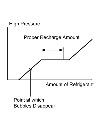 |
The point at which the air bubbles disappear in the refrigerant of the sub-cool cycle is lower than the proper amount of refrigerant with which the system must be filled. Therefore, if the system is recharged with refrigerant based on the point at which the air bubbles disappear, the amount of refrigerant would be insufficient. As a result, the cooling performance of the system would be affected. If the system is overcharged with refrigerant, this will also lead to reduced performance. For the proper method of verifying the amount of the refrigerant and for instructions on how to recharge the system with refrigerant.
| Compressor with Motor Assembly |
General
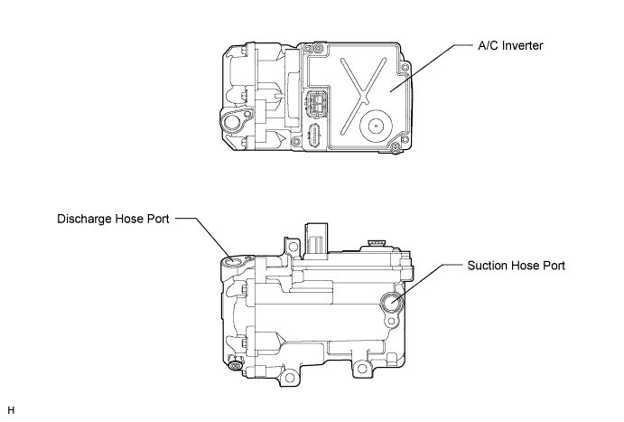
Construction
| Ambient Temperature Sensor |
The ambient temperature sensor detects the ambient temperature based on changes in the resistance of its built-in thermistor. This signal is used by the air conditioning amplifier.
| Heater Water Pump |
A heater water pump is used to circulate coolant for the heater core. This provides stable heater performance even if the engine is stopped due to THS-II control.
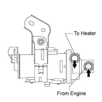 |
A pump with low resistance to water flow is used.
| Compressor Control (Compressor Speed Control) |
The air conditioning amplifier calculates the target compressor speed. Then, the air conditioning amplifier transmits the target compressor speed to the hybrid vehicle control ECU. The hybrid vehicle control ECU controls the air conditioning inverter based on the target speed data. This control is performed in order make the compressor operate at a speed that suits the operating conditions of the air conditioning system.
The air conditioning amplifier calculates the target evaporator temperature, which includes . Accordingly, the air conditioning amplifier controls the compressor speed to an extent that does not inhibit the proper cooling performance or defogging performance. As a result, comfort and low fuel consumption can be realized.