 |
Using a socket hexagon wrench 10 mm, remove the filler plug and gasket.
FRONT DRIVE SHAFT > REMOVAL |
| 1. REMOVE NO. 1 ENGINE UNDER COVER |
Remove the 6 bolts, 2 screws, 2 clips and No. 1 engine under cover.
| 2. REMOVE NO. 2 ENGINE UNDER COVER |
Remove the 4 bolts and No. 2 engine under cover.
| 3. DRAIN HYBRID TRANSAXLE FLUID |
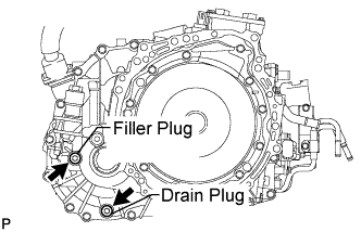
|
Using a socket hexagon wrench 10 mm, remove the filler plug and gasket.
Using a socket hexagon wrench 10 mm, remove the drain plug and gasket.
Using a socket hexagon wrench 10 mm, install the drain plug, and a new gasket.
| 4. REMOVE FRONT WHEELS |
| 5. REMOVE FRONT AXLE SHAFT NUT LH |
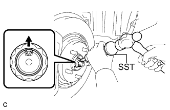 |
Using SST and a hammer, release the staked part of the front axle shaft nut LH.
While applying the brakes, remove the front axle shaft nut LH.
| 6. SEPARATE FRONT STABILIZER LINK ASSEMBLY LH |
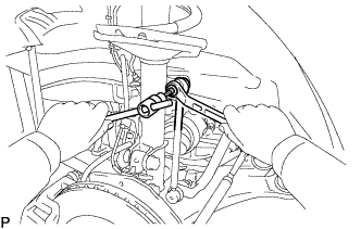 |
Remove the nut and separate the front stabilizer link assembly from the front shock absorber.
| 7. SEPARATE FRONT SPEED SENSOR LH |
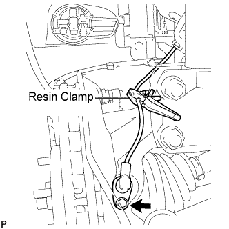 |
Remove the bolt and resin clamp, and separate the front speed sensor.
| 8. SEPARATE TIE ROD ASSEMBLY LH |
Remove the cotter pin and the nut.
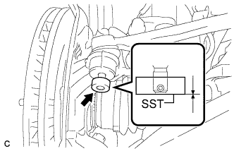 |
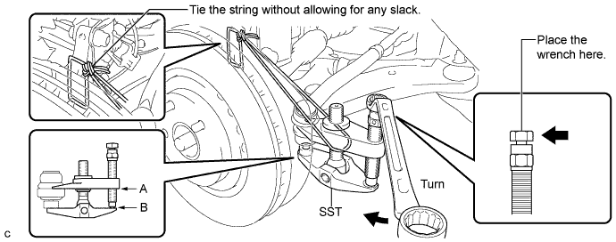
Install SST to the tie rod end.
Using SST, separate the tie rod end from the steering knuckle.
| 9. SEPARATE NO. 1 FRONT SUSPENSION LOWER ARM LH |
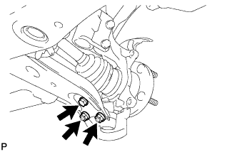 |
Remove the bolt and 2 nuts, and separate the front lower suspension arm from the front lower ball joint.
| 10. SEPARATE FRONT AXLE ASSEMBLY LH |
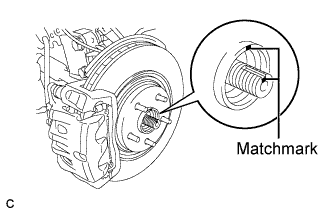 |
Put matchmarks on the front drive shaft assembly and the front axle hub sub-assembly.
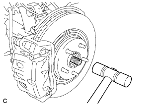 |
Using a plastic hammer, separate the front drive shaft assembly from the front axle assembly.
| 11. REMOVE FRONT DRIVE SHAFT ASSEMBLY LH |
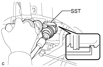 |
Using SST, remove the front drive shaft assembly LH.
| 12. REMOVE FRONT DRIVE SHAFT ASSEMBLY RH |
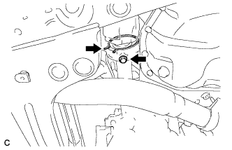 |
Remove the bearing bracket hole snap ring from the drive shaft bearing bracket.
Remove the bolt and front drive shaft assembly RH from the drive shaft bearing bracket.
| 13. SECURE FRONT AXLE HUB SUB-ASSEMBLY LH |
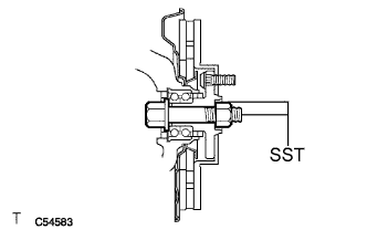 |
Using SST, secure the front axle hub bearing.