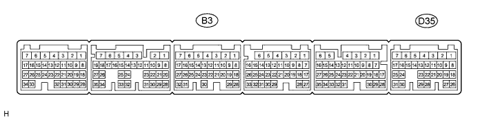
Symbols (Terminal No.)
| Wiring Color
| Terminal Description
| Condition
| Specified Condition
|
D35-31 (STP) - B3-5 (E1)
| R - W-B
| Stop light signal
| Power switch on (IG), Brake pedal depressed
| 11 to 14 V
|
D35-31 (STP) - B3-5 (E1)
| R - W-B
| Stop light signal
| Power switch on (IG), Brake pedal released
| Below 1 V
|
D35-25 (ST1-) - B3-5 (E1)
| LG - W-B
| Stop light signal
| Power switch on (IG), Brake pedal depressed
| Below 1 V
|
D35-25 (ST1-) - B3-5 (E1)
| LG - W-B
| Stop light signal
| Power switch on (IG), Brake pedal released
| 11 to 14 V
|
D35-3 (TC) - B3-5 (E1)
| L - W-B
| Terminal TC of DLC3
| Power switch on (IG)
| 11 to 14 V
|
D35-3 (TC) - B3-5 (E1)
| L - W-B
| Terminal TC of DLC3
| Terminals TC and CG of DLC3 connected
| Below 1 V
|
D35-24 (SPDI) - B3-5 (E1)
| G - W-B
| Vehicle speed signal
| Engine start → car stoppage
| Below 1.5 V → 4.7 to 16 V
|
D35-24 (SPDI) - B3-5 (E1)
| G - W-B
| Vehicle speed signal
| during pedal released
(Pulse generated)
| 3 to 7 V
|
D35-26 (CCS) - B3-5 (E1)
| L - W-B
| Cruise control main switch circuit
| Power switch on (IG)
| 11 to 14 V
|
D35-26 (CCS) - B3-5 (E1)
| L - W-B
| Cruise control main switch circuit
| CANCEL switch ON
| 6.6 to 10.1 V
|
D35-26 (CCS) - B3-5 (E1)
| L - W-B
| Cruise control main switch circuit
| -/SET switch ON
| 4.5 to 7.1 V
|
D35-26 (CCS) - B3-5 (E1)
| L - W-B
| Cruise control main switch circuit
| +/RES switch ON
| 2.3 to 4.0 V
|
D35-26 (CCS) - B3-5 (E1)
| L - W-B
| Cruise control main switch circuit
| MAIN switch ON
| Below 1 V
|
B3-9 (D) - B3-5 (E1)
| Y - W-B
| D shift position signal
| Power switch on (IG), shift lever in any position except D position
| Below 1 V
|
B3-9 (D) - B3-5 (E1)
| Y - W-B
| D shift position signal
| Power switch on (IG), shift lever in D position
| 11 to 14 V
|