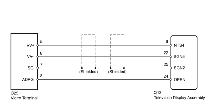
REAR SEAT ENTERTAINMENT SYSTEM > Display Signal Circuit between Video Terminal and Television Display |
| 1.CHECK HARNESS AND CONNECTOR (TELEVISION DISPLAY ASSEMBLY - VIDEO TERMINAL) |
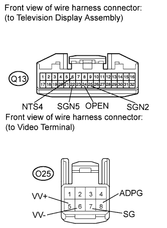 |
Disconnect the television display assembly connector.
Disconnect the video terminal connector.
Measure the resistance according to the value(s) in the table below.
| Tester Connection | Condition | Specified Condition |
| Q13-6 (NTS4) - O25-5 (VV+) | Always | Below 1 Ω |
| Q13-22 (SGN5) - O25-6 (VV-) | Always | Below 1 Ω |
| Q13-25 (SGN2) - O25-7 (SG) | Always | Below 1 Ω |
| Q13-24 (OPEN) - O25-8 (ADPG) | Always | Below 1 Ω |
| Q13-6 (NTS4) - Body ground | Always | 10 kΩ or higher |
| Q13-22 (SGN5) Body ground | Always | 10 kΩ or higher |
| Q13-25 (SGN2) - Body ground | Always | 10 kΩ or higher |
| Q13-24 (OPEN) - Body ground | Always | 10 kΩ or higher |
|
| ||||
| OK | |
 |
| 2.INSPECT VIDEO TERMINAL |
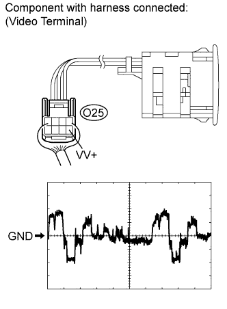 |
Using an oscilloscope, check the waveform of the video terminal.
| Item | Content |
| Symbols (Terminal No.) | O25-5 (VV+) - Body ground |
| Tool Setting | 200 mV/DIV., 10 μsec./DIV. |
| Condition | RSE system playing |
|
| ||||
| OK | ||
 | ||
| ||
