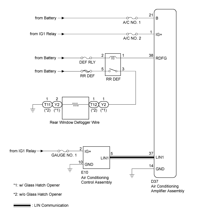
WINDOW DEFOGGER SYSTEM > Rear Window Defogger System does not Operate |
| 1.CHECK FUSES (RR DEF) |
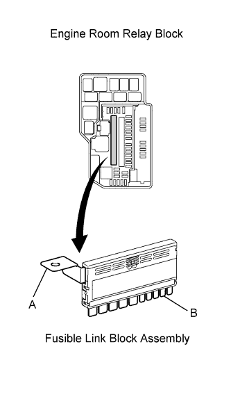 |
Remove the fusible link block assembly (RR DEF) from the engine room relay block.
Measure the resistance according to the value(s) in the table below.
| Tester Connection | Condition | Specified Condition |
| A - B (RR DEF) | Always | Below 1 Ω |
|
| ||||
| OK | |
 |
| 2.INSPECT DEFOGGER RELAY (Marking: RR DEF) |
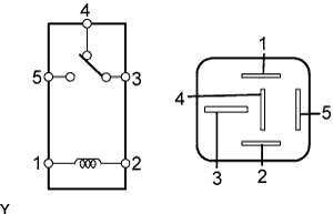 |
Remove the defogger relay (Marking: RR DEF) from the engine room relay block.
Measure the resistance according to the value(s) in the table below.
| Tester Connection | Condition | Specified Condition |
| 3 - 4 | Voltage is not applied between terminals 1 and 2 | Below 1 Ω |
| 3 - 4 | Apply battery voltage between terminals 1 and 2 | 10 kΩ or higher |
| 3 - 5 | Voltage is not applied between terminals 1 and 2 | 10 kΩ or higher |
| 3 - 5 | Apply battery voltage between terminals 1 and 2 | Below 1 Ω |
|
| ||||
| OK | |
|
| 3.PERFORM ACTIVE TEST USING TECHSTREAM |
Select the Active Test, use the Techstream to issue a control command, and then check the window defogger operation.
| Tester Display | Test Part | Control Range | Diagnostic Note |
| Defogger Relay (Rear) | Rear window defogger | OFF/ON | - |
| Result | Proceed to |
| The window defogger system does not operate normally when operating it through the Techstream. | A |
| The window defogger system operates normally when operating it through the Techstream. | B |
|
| ||||
| B | |
|
| 4.CHECK HARNESS AND CONNECTOR (LIN COMMUNICATION LINE) |
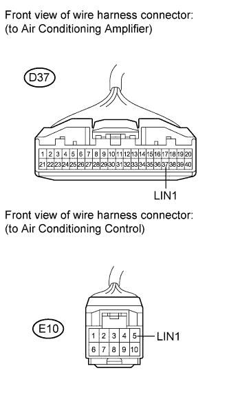 |
Disconnect the D37 air conditioning amplifier connector.
Disconnect the E10 air conditioning control connector.
Measure the resistance according to the value(s) in the table below.
| Tester Connection | Condition | Specified Condition |
| D37-37 (LIN1) - E10-5 (LIN1) | Always | Below 1 Ω |
| D37-37 (LIN1) - Body ground | Always | 10 kΩ or higher |
|
| ||||
| OK | |
|
| 5.REPLACE AIR CONDITIONING CONTROL ASSEMBLY |
for Automatic Air Conditioning System
Replace the air conditioning control assembly (Click here).
for Manual Air Conditioning System
Replace the air conditioning control assembly (Click here).
| NEXT | |
|
| 6.CONFIRM REAR WINDOW DEFOGGER OPERATION |
Turn the power switch on (IG), press the defogger switch, and check that the window defogger operates.
|
| ||||
| OK | ||
 | ||
| ||
| 7.PERFORM ACTIVE TEST USING TECHSTREAM |
Select the Active Test, use the Techstream to issue a control command, and then check the window defogger operation.
| Tester Display | Test Part | Control Range | Diagnostic Note |
| Defogger Relay (Rear) | Rear window defogger | OFF/ON | - |
Check that operation sound of the DEFOGGER relay (Marking: RR DEF) is heard.
| Result | Proceed to |
| Relay operating sound is heard | A |
| Relay operating sound is not heard | B |
|
| ||||
| B | |
|
| 8.CHECK HARNESS AND CONNECTOR (A/C AMPLIFIER ASSEMBLY - ENGINE ROOM RELAY BLOCK) |
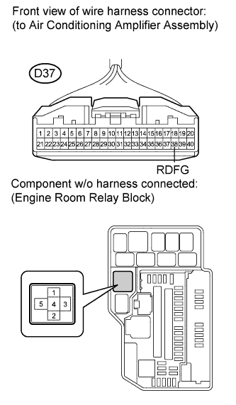 |
Disconnect the D37 air conditioning amplifier connector.
Disconnect the defogger relay (Marking: RR DEF) engine room relay block .
Measure the resistance according to the value(s) in the table below.
| Tester Connection | Condition | Specified Condition |
| D37-38 (RDFG) - 2 | Always | Below 1 Ω |
| D37-38 (RDFG) - Body ground | Always | 10 kΩ or higher |
|
| ||||
| OK | |
|
| 9.CHECK HARNESS AND CONNECTOR (RDFG TERMINAL BATTERY VOLTAGE) |
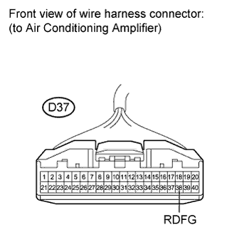 |
Reconnect the defogger relay (Marking: RR DEF) engine room relay block .
Measure the voltage according to the value(s) in the table below.
| Tester Connection | Condition | Specified Condition |
| D37-38 (RDFG) - Body ground | Power switch on (IG) | 11 to 14 V |
|
| ||||
| OK | ||
| ||
| ||
| 10.CHECK HARNESS AND CONNECTOR (REAR WINDOW DEFOGGER WIRE - ENGINE ROOM RELAY BLOCK) |
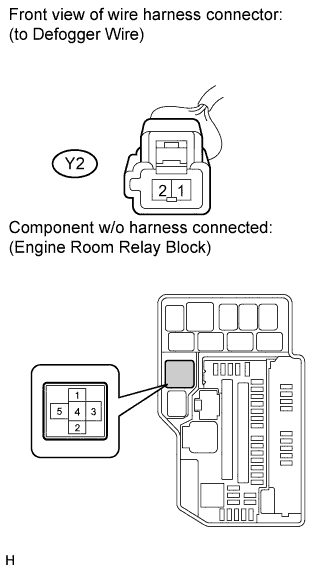 |
w/ Glass Hatch Opener
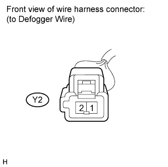
Disconnect the Y2 connector.
Remove the defogger relay (Marking: RR DEF) from the engine room relay block.
Measure the resistance according to the value(s) in the table below.
| Tester Connection | Condition | Specified Condition |
| Y2-1 - 3 | Always | Below 1 Ω |
| Y2-1 - Body ground | Always | 10 kΩ or higher |
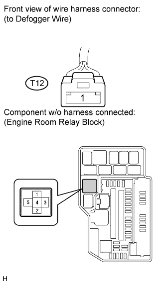 |
w/o Glass Hatch Opener
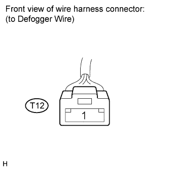
Disconnect the T12 connector.
Remove the defogger relay (Marking: RR DEF) from the engine room relay block.
Measure the resistance according to the value(s) in the table below.
| Tester Connection | Condition | Specified Condition |
| T12-1 - 3 | Always | Below 1 Ω |
| T12-1 - Body ground | Always | 10 kΩ or higher |
|
| ||||
| OK | |
|
| 11.CHECK HARNESS AND CONNECTOR (REAR WINDOW DEFOGGER WIRE BATTERY POSITIVE) |
 |
w/ Glass Hatch Opener
Reconnect the defogger relay (Marking: RR DEF) from the engine room relay block.
Measure the voltage according to the value(s) in the table below.
| Tester Connection | Condition | Specified Condition |
| Y2-1 - Body ground | Power switch on (IG) Rear window defogger switch on | 11 to 14 V |
 |
w/o Glass Hatch Opener
Reconnect the defogger relay (Marking: RR DEF) from the engine room relay block.
Measure the voltage according to the value(s) in the table below.
| Tester Connection | Condition | Specified Condition |
| T12-1 - Body ground | Power switch on (IG) Rear window defogger switch on | 11 to 14 V |
|
| ||||
| OK | |
|
| 12.CHECK HARNESS AND CONNECTOR (REAR WINDOW DEFOGGER WIRE CONNECTOR - BODY GROUND) |
|
w/ Glass Hatch Opener
Disconnect the Y2 connector.
Measure the resistance according to the value(s) in the table below.
| Tester Connection | Condition | Specified Condition |
| Y2-1 - Body ground | Always | Below 1 Ω |
 |
w/o Glass Hatch Opener
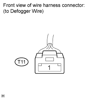
Disconnect the T11 connector.
Measure the resistance according to the value(s) in the table below.
| Tester Connection | Condition | Specified Condition |
| T11-1 - Body ground | Always | Below 1 Ω |
|
| ||||
| OK | ||
| ||
| ||

