Home › ENGINE › 3MZ-FE STARTING › SMART KEY SYSTEM

DTC    B2289    Key Collation Waiting Time Over

for Preparation Click here


DESCRIPTION

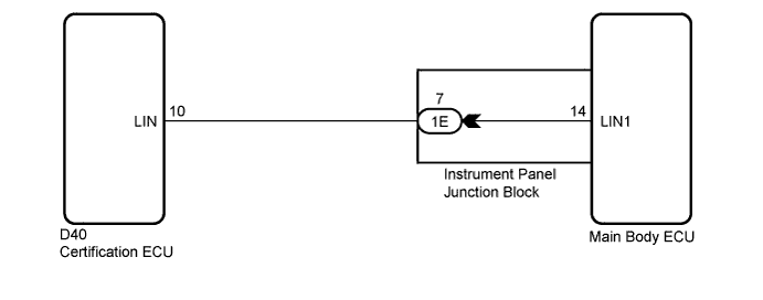
This DTC is output when there is a LIN communication problem between the main body ECU (instrument panel junction block) and certification ECU (smart key ECU assembly) or when there is a problem in the entry function.

HINT:
If the main body ECU (instrument panel junction block) is replaced with a new one while the negative (-) battery terminal is connected, the power source mode will be in IG-ON mode. When the battery is removed and reinstalled, the power source mode that was selected when the battery was removed is restored. After the main body ECU (instrument panel junction block) is replaced, perform the registration procedure for the engine immobiliser system (Click here).


DTC No.
DTC Detection Condition
Trouble Area
B2289
Either condition below is met:
  1. LIN communication is abnormal between the main body ECU (instrument panel junction block) and the certification ECU (smart key ECU assembly)
  2. The engine immobiliser system is malfunctioning
  1. Main body ECU (instrument panel junction block)
  2. Smart key system (entry)
  3. Wire harness or connector
  4. Certification ECU (smart key ECU assembly)

WIRING DIAGRAM


B177341E01


INSPECTION PROCEDURE

1.CHECK FOR DTC
  1. Check for DTCs (Click here).

  1. Proceed to the next step based on the inspection result.

    Result:

    Result
    Proceed to
    DTC B2289 only
    A
    LIN communication system DTCs are output
    B
    Engine immobiliser system DTCs are output
    C


B
GO TO DIAGNOSTIC TROUBLE CODE CHART (LIN COMMUNICATION SYSTEM) (Click here)

C
GO TO DIAGNOSTIC TROUBLE CODE CHART (ENGINE IMMOBILISER SYSTEM) (Click here)
A


2.CHECK SMART KEY SYSTEM


  1. Remove the battery of the electrical key transmitter (Click here).
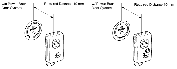

    B183999E01

  1. Touch the logo side mark of the key or card key to the power switch.

  1. Check that the power switch can be turned on (IG).

    OK:
    Power source mode is turned on


NG
Go to step 3
OK

GO TO SMART KEY SYSTEM (ROOM OSCILLATOR DOES NOT RECOGNIZE KEY) (Click here)  

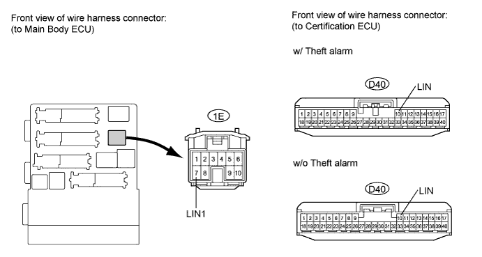
3.CHECK HARNESS AND CONNECTOR (INSTRUMENT PANEL JUNCTION BLOCK - CERTIFICATION ECU)


  1. Disconnect the D40 and 1E connectors.


    B184075E01

  1. Measure the resistance according to the value(s) in table below.

    Standard resistance:
    Tester Connection
    Condition
    Specified Condition
    1E-7 (LIN) - D40-10
    Always
    Below 1Ω
    1E-7 (LIN) or D40-10 (LIN) - Body ground
    Always
    10 kΩ or higher


NG
REPAIR OR REPLACE HARNESS OR CONNECTOR
OK


4.REPLACE MAIN BODY ECU
  1. Replace main body ECU.


NEXT


5.CHECK FOR DTCS
  1. Delete the DTCs (Click here).

  1. Check for DTC B2289 (Key collection waiting time over).

    OK:
    DTC B2289 is not output.


NG
Go to step 6
OK

END 

6.REPLACE CERTIFICATION ECU (SMART KEY ECU)
  1. Replace certification ECU (smart key ECU) (Click here).


NEXT


7.KEY REGISTRATION
  1. Register the key (Click here).


NEXT

END