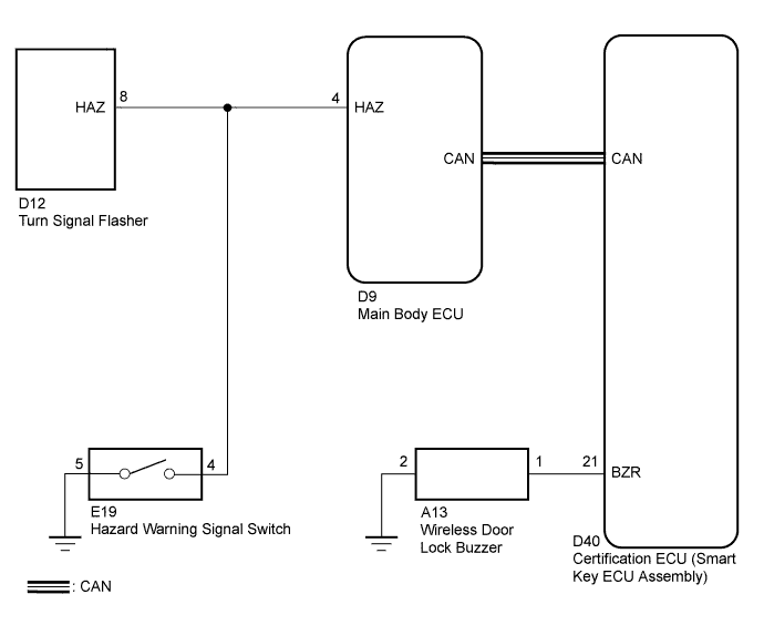
WIRELESS DOOR LOCK CONTROL SYSTEM > No Answer-Back |
| 1.CHECK WIRELESS DOOR LOCK CONTROL FUNCTION |
Check the wireless door lock control functions by operating the transmitter switch.
| Result | Proceed to |
| Wireless door lock functions are normal but hazard warning lights answer-back does not occur | A |
| Wireless door lock functions are normal but wireless door lock buzzer answer-back does not occur | B |
| Doors cannot be locked and unlocked with transmitter | C |
|
| ||||
|
| ||||
| A | |
 |
| 2.CHECK HAZARD WARNING LIGHT |
Check that the hazard warning lights flash continuously when the hazard warning signal switch is pressed.
|
| ||||
| OK | |
|
| 3.PERFORM ACTIVE TEST USING TECHSTREAM (TURN SIGNAL FLASHER) |
Select an Active Test, use the Techstream to generate a control command, and then check that the hazard warning lights flash.
| Tester Display | Test Part | Control Range | Diagnostic Note |
| Hazard | Turn Signal Flasher | ON/OFF | - |
|
| ||||
| OK | |
|
| 4.REPLACE MAIN BODY ECU |
Replace the main body ECU.
| NEXT | |
|
| 5.CHECK HAZARD WARNING LIGHTS |
Check that the hazard warning lights flash continuously when the door control transmitter LOCK or UNLOCK switch is pressed.
|
| ||||
| OK | ||
 | ||
| ||
| 6.PERFORM ACTIVE TEST USING TECHSTREAM (WIRELESS DOOR LOCK BUZZER) |
Select the Active Test, use the Techstream to generate a control command, and then check that the wireless buzzer operate normally.
| Tester Display | Test Part | Control Range | Diagnostic Note |
| Wireless Buzzer | Wireless Door Lock Buzzer | ON/OFF | - |
|
| ||||
| OK | ||
| ||
| ||
| 7.INSPECT WIRELESS DOOR LOCK BUZZER |
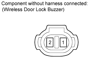 |
Measure the resistance according to the value(s) in the table below.
| Tester Connection | Condition | Specified Condition |
| 1 - 2 | Always | 950 to 1050 Ω |
|
| ||||
| OK | |
|
| 8.CHECK WIRE HARNESS (WIRELESS DOOR LOCK BUZZER - CERTIFICATION ECU AND BODY GROUND) |
Disconnect the A13 buzzer connector.
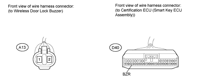
Disconnect the D40 certification ECU (smart key ECU assembly) connector.
Measure the resistance of the wire harness side connectors.
| Tester Connection | Condition | Specified Condition |
| A13-1 - D40-21 (BZR) | Always | Below 1 Ω |
| A13-2 - Body ground | Always | Below 1 Ω |
| A13-1 - Body ground | Always | 10 kΩ or higher |
|
| ||||
| OK | ||
| ||
| ||

