 |
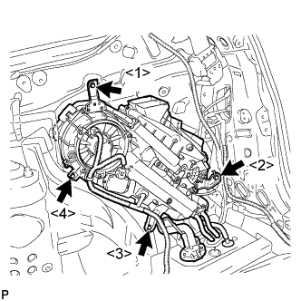
Install the rear cooling unit assembly with the 4 bolts.
- Torque:
- 9.8 N*m{ 100 kgf*cm , 87 in.*lbf }
- HINT:
- Tighten the bolts in the order shown in the illustration.
REAR COOLING UNIT > INSTALLATION |
| 1. INSTALL REAR COOLING UNIT ASSEMBLY |
|
Install the rear cooling unit assembly with the 4 bolts.
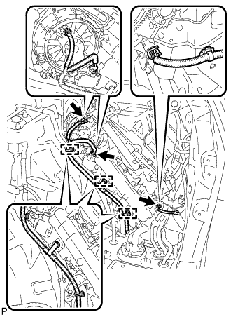 |
Connect each connector.
Engage each clamp.
| 2. INSTALL REAR NO. 5 AIR DUCT |
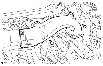 |
Install the rear No. 5 air duct with the 2 clips.
| 3. INSTALL NO. 1 COOLER AIR DUCT |
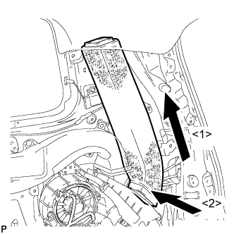 |
Install the No. 1 cooler air duct as shown in the illustration.
| 4. INSTALL COOLER PLATE |
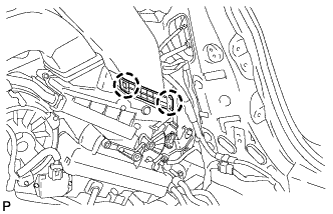 |
Engage the 2 claws and install the cooler plate.
| 5. INSTALL ROOF SIDE INNER GARNISH ASSEMBLY RH |
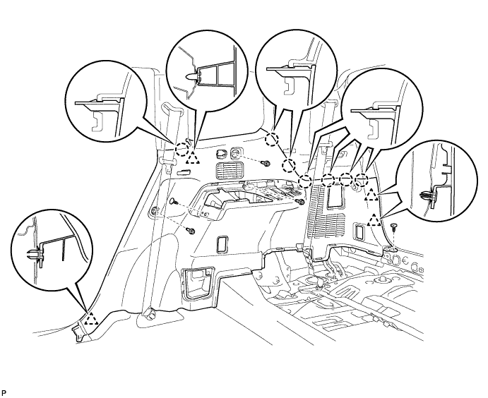
| 6. INSTALL DECK TRIM SIDE PANEL ASSEMBLY RH |
Engage the 4 clips and the 7 claws.
Install the 2 clips.
Install the deck trim side panel assembly RH with the 3 bolts.
| 7. INSTALL FRONT DECK SIDE TRIM COVER RH |
| 8. INSTALL NO. 1 LUGGAGE COMPARTMENT TRIM HOOK |
| 9. INSTALL ROPE HOOK ASSEMBLY (for RH Side) |
| 10. INSTALL REAR COMBINATION LIGHT SERVICE COVER RH |
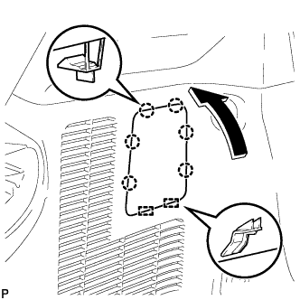 |
Engage the 2 guides and 6 claws, and install the rear combination light service cover RH.
| 11. INSTALL SIDE TRIM COVER RH (for Manual Air Conditioning System) |
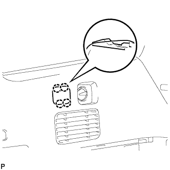 |
Engage the 4 claws, and install the side trim cover RH.
| 12. INSTALL REAR ROOM TEMPERATURE SENSOR (for Automatic Air Conditioning System) |
Connect the connector.
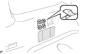 |
Engage the 4 claws and install the rear room temperature sensor.
| 13. INSTALL DECK SIDE TRIM RH |
| 14. INSTALL DECK SIDE TRIM COVER RH |
| 15. INSTALL REAR SEAT SIDE GARNISH CAP |
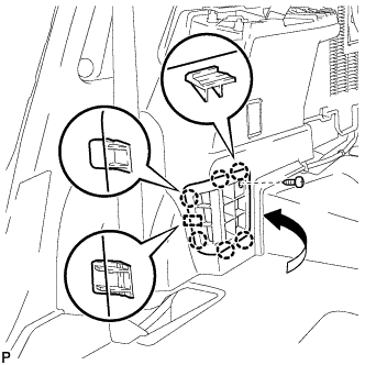 |
Engage the guide and the 6 claws.
Install the rear seat side garnish cap with the screw.
| 16. INSTALL REAR FLOOR FINISH PLATE |
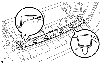 |
Engage the 4 clips and the 4 claws, and install the rear floor finish plate.
| 17. INSTALL REAR NO. 2 SEAT ASSEMBLY |
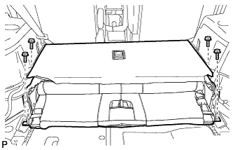 |
Install the rear No. 2 seat assembly with the 4 bolts.
| 18. CONNECT REAR SEAT LAP TYPE BELT ASSEMBLY LH |
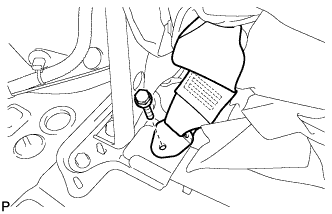 |
Install the rear seat lap type belt assembly LH with the bolt.
| 19. CONNECT REAR SEAT LAP TYPE BELT ASSEMBLY RH |
Install the rear seat lap type belt assembly RH with the bolt.
| 20. INSTALL REAR NO. 2 SEAT INNER BELT ASSEMBLY |
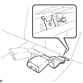 |
Install the rear No. 2 seat inner belt assembly with the bolt.
| 21. INSTALL REAR MAT |
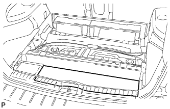 |
Install the rear mat.
| 22. INSTALL DECK FLOOR BOARD ASSEMBLY |
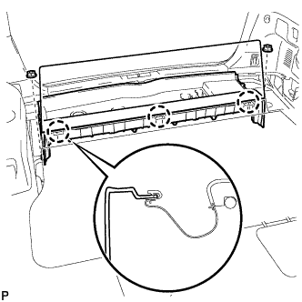 |
Install the 2 nuts and the deck floor board assembly.
Engage the 3 claws.
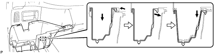
| 23. INSTALL DECK SIDE TRIM BOX LH |
Install the deck side trim box LH as shown in the illustration.
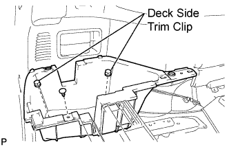 |
Install the 2 deck side trim clip and the clips.
| 24. INSTALL REAR SEAT SIDE COVER LH |
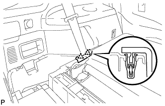 |
Engage the 2 clips and install the rear seat side cover LH.
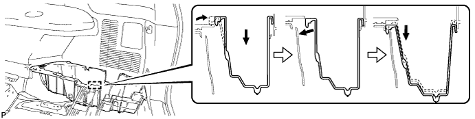
| 25. INSTALL DECK SIDE TRIM BOX RH |
Install the deck side trim box RH as shown in the illustration.
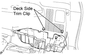 |
Install the 2 deck side trim clip and the clips.
| 26. INSTALL JACK CARRIER ASSEMBLY |
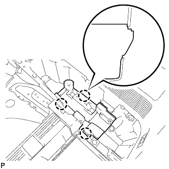 |
Engage the 3 claws, and install the jack carrier assembly.
| 27. INSTALL JACK ASSEMBLY |
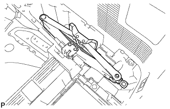 |
Install the jack assembly.
| 28. INSTALL JACK CARRIER CUSHION |
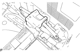 |
Install the jack carrier cushion.
| 29. INSTALL JACK CARRIER SUPPORT |
| 30. INSTALL REAR SEAT SIDE COVER RH |
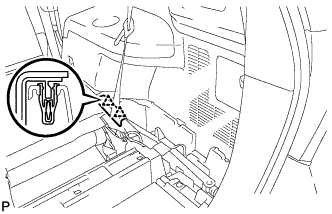 |
Engage the 2 clips and install the rear seat side cover RH.
| 31. INSTALL TONNEAU COVER ASSEMBLY (w/ Tonneau Cover) |
Install the tonneau cover assembly.
| 32. INSTALL NO. 2 DECK BOARD SUB-ASSEMBLY |
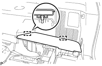 |
Engage the 2 guides and install the No. 2 deck board sub-assembly.
| 33. INSTALL NO. 3 DECK BOARD SUB-ASSEMBLY |
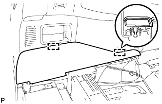 |
Engage the 2 guides and install the No. 3 deck board sub-assembly.
| 34. INSTALL DECK BOARD ASSEMBLY |
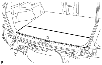 |
Install the deck board assembly.
| 35. INSTALL REAR DOOR OPENING TRIM WEATHERSTRIP RH |
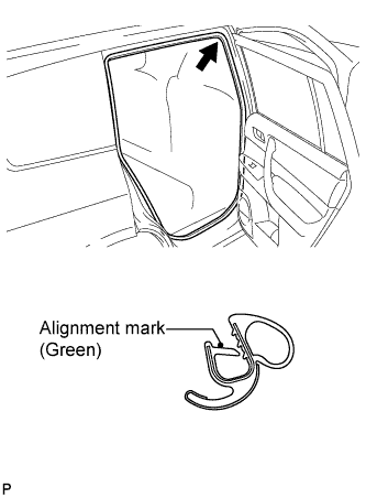 |
Align the alignment mark (green) on the weatherstrip with the protruding portion on the body indicated by the arrow in the illustration, and install the rear door opening trim weatherstrip RH.
| 36. INSTALL REAR DOOR SCUFF PLATE RH |
| 37. CONNECT COOLER REFRIGERANT LIQUID PIPE C |
Remove the attached vinyl tape from the pipe C.
Sufficiently apply compressor oil to a new O-ring and the fitting surface of the cooler refrigerant liquid pipe C.
Install the O-ring on the cooler refrigerant liquid pipe C.
Install the cooler refrigerant liquid pipe C.
| 38. CONNECT COOLER REFRIGERANT SUCTION HOSE |
Remove the attached vinyl tape from the hose.
Sufficiently apply compressor oil to a new O-ring and the fitting surface of the cooler refrigerant suction hose.
Install the O-ring on the cooler refrigerant suction hose.
Move the hook connector in the direction indicated by the arrow in the illustration.
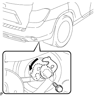 |
Insert the pipe joint into the fitting hole securely and tighten the bolt.
| 39. CONNECT REAR HEATER INLET WATER HOSE |
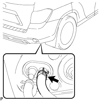 |
Install the water hose and attach the clip.
| 40. CONNECT REAR HEATER OUTLET WATER HOSE |
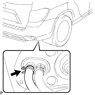 |
Install the water hose and attach the clip.
| 41. CHARGE WITH REFRIGERANT |
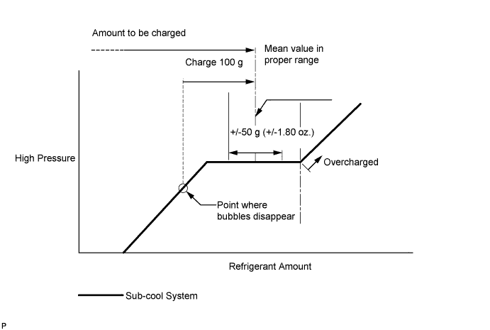
Perform vacuum purging using a vacuum pump.
Charge with refrigerant HFC-134a (R134a).
| 42. ADD ENGINE COOLANT (for Engine) |
Tighten the radiator drain cock plug.
Tighten the cylinder block drain cock plugs.
Loosen the air drain plug.
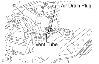 |
Install a vinyl tube to the vent tube located on the air drain plug.
Fill the radiator with engine coolant until the vinyl tube is filled with the coolant.
Tighten the air drain plug.
| Condition | Capacity |
| w/ rear heater | 12.8 liters (13.5 US qts, 11.2 lmp.qts) |
| w/o rear heater | 10.6 liters (11.2 US qts, 9.3 lmp.qts) |
Install the radiator cap securely.
Fill the radiator reservoir tank with coolant.
Warm up the engine until the thermostat opens. While the thermostat is open, allow the coolant to circulate for several minutes.
Stop the engine and wait until the coolant cools down.
Remove the radiator cap and check the coolant level inside the radiator.
If the coolant level is below the full level, perform the steps from (C) through (K) and repeat the operation until the coolant level stays at the full level.
Recheck the coolant level inside the radiator reservoir tank. If it is below the full level, add the coolant.
| 43. INSPECT FOR COOLANT LEAK (for Engine) |
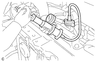 |
Fill the radiator with coolant and attach a radiator cap tester.
Pump the tester to 118 kPa (1.2 kgf/cm2, 17.1 psi), then check that the pressure does not drop.
If the pressure drops, check the hoses, radiator assembly and water pump assembly for leakage. If there are no signs or traces of external engine coolant leakage, check the heater core, cylinder block and cylinder head.
| 44. WARM UP ENGINE |
Keep the A/C switch on for at least 2 minutes to warm up the compressor.
| 45. INSPECT FOR REFRIGERANT LEAK |
After recharging with refrigerant gas, inspect for a refrigerant leak using a halogen leak detector.
Carry out the test under the following conditions:
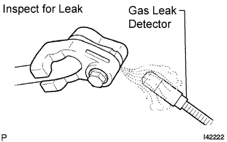 |
Using a gas leak detector, inspect for a leak from the refrigerant lines.
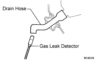 |
Bring the gas leak detector close to the drain hose with the detector's power off, and then turn the detector on.
If a gas leak is not detected from the drain hose, remove the blower motor control from the cooling unit. Insert the gas leak detector sensor into the unit and perform the test.
Disconnect the pressure switch connector and leave it for approximately 20 minutes. Bring the gas leak detector close to the pressure switch and perform the test.