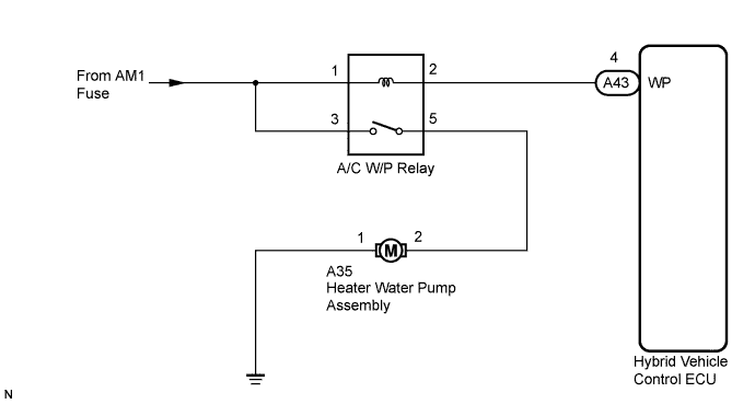
AIR CONDITIONING SYSTEM (for Manual Air Conditioning System) > Heater Water Pump Circuit |
| 1.CHECK CAN COMMUNICATION SYSTEM |
Using the Techstream, check if the CAN communication system is functioning normally.
| Result | Proceed to |
| CAN DTC is not output | A |
| CAN DTC is output | B |
|
| ||||
| A | |
 |
| 2.PERFORM ACTIVE TEST USING TECHSTREAM |
Connect the Techstream to the DLC3.
Turn the power switch on (IG) and turn the Techstream on.
Select the item below in the Active Test and check that the relay operates.
| Tester Display | Test Part | Control Range | Diagnostic Note |
| Water Pump | Water pump relay | OFF, ON | - |
|
| ||||
| OK | ||
 | ||
| ||
| 3.INSPECT RELAY (A/C W/P) |
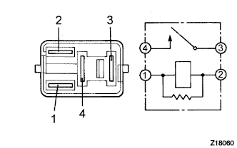 |
Remove the A/C W/P relay from the engine room relay block and No. 1 junction block.
Measure the resistance according to the value(s) in the table below.
| Tester Connection | Specified Condition |
| 3 - 5 | 10 kΩ or higher |
| 3 - 5 | Below 1 Ω (When battery voltage is applied to terminals 1 and 2) |
|
| ||||
| OK | |
|
| 4.CHECK HARNESS AND CONNECTOR (HYBRID VEHICLE CONTROL ECU - BATTERY) |
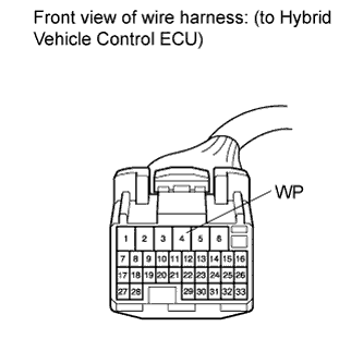 |
Disconnect the connector from the hybrid vehicle control ECU.
Measure the voltage according to the value(s) in the table below.
| Tester Connection (Symbols) | Switch Condition | Specified Condition |
| A43-4 (WP) - Body ground | Power switch off | Below 1 V |
| A43-4 (WP) - Body ground | Power switch on (IG) | 11 to 14 V |
|
| ||||
| OK | |
|
| 5.CHECK HARNESS AND CONNECTOR (BATTERY - ENGINE ROOM R/B AND J/B NO. 1) |
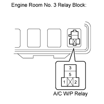 |
Remove the A/C W/P relay from the engine room relay block and No. 1 junction block.
Measure the voltage according to the value(s) in the table below.
| Tester Connection (Symbols) | Switch Condition | Specified Condition |
| Relay block A/C W/P relay terminal 5 - Body ground | Power switch on (IG) | 11 to 14 V |
| Relay block A/C W/P relay terminal 5 - Body ground | Power switch off | Below 1 V |
|
| ||||
| OK | |
|
| 6.INSPECT HEATER WATER PUMP ASSEMBLY |
Disconnect the connector from the heater water pump assembly.
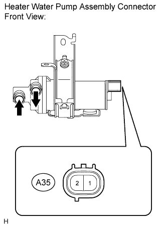 |
Connect a positive (+) lead from the battery to terminal 1 and a negative (-) lead to terminal 2.
|
| ||||
| OK | |
|
| 7.CHECK HARNESS AND CONNECTOR (HEATER WATER PUMP ASSEMBLY - BODY GROUND) |
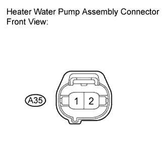 |
Measure the resistance according to the value(s) in the table below.
| Tester Connection | Condition | Specified Condition |
| A35-2 - Body ground | Always | Below 1 Ω |
|
| ||||
| OK | |
|
| 8.CHECK HARNESS AND CONNECTOR (HEATER WATER PUMP ASSEMBLY - ENGINE ROOM R/B AND J/B NO. 1) |
|
Remove the A/C W/P relay from the engine room relay block and No. 1 junction block.
|
Measure the resistance according to the value(s) in the table below.
| Tester Connection | Condition | Specified Condition |
| A35-1 - Relay block A/C W/P relay terminal 3 | Always | Below 1 Ω |
| A35-1 - Body ground | Always | 10 kΩ or higher |
|
| ||||
| OK | |
|
| 9.REPLACE AIR CONDITIONING AMPLIFIER |
Replace the air conditioning amplifier with a normal one and check if the same problem occurs again.
|
| ||||
| OK | ||
| ||
| ||

