Home › HEATER & AIR CONDITIONING SYSTEM › AIR CONDITIONING › CONDENSER

CONDENSER > INSTALLATION

for Preparation Click here


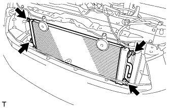
1. INSTALL COOLER CONDENSER ASSEMBLY


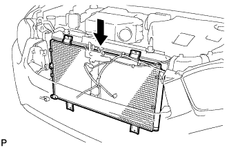
    E153504
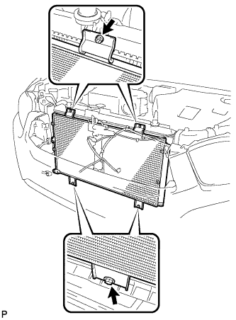
  1. Install the cooler condenser assembly as shown in the illustration.


    E153502
  1. Install the 4 bolts.

    HINT:
    If the condenser is replaced with a new one, add compressor oil to the new condenser.

    Capacity:
    40 cc (1.4 fl.oz.)

    Compressor oil:
    ND-11 or equivalent

    NOTICE:
    Do not use any compressor oil other than ND-OIL 11 or equivalent. If any compressor oil other than ND-OIL 11 or equivalent is used, compressor motor insulation performance may decrease, resulting in a leakage of electric power.


2. CONNECT COOLER REFRIGERANT LIQUID PIPE A
  1. Remove the attached vinyl tape from the tube and the connecting part of the cooler condenser assembly.

  1. Sufficiently apply compressor oil to a new O-ring and the fitting surface of the tube joint.

    Compressor oil:
    ND-OIL 11 or equivalent

    NOTICE:
    1. Keep the O-rings and O-ring fitting surfaces clean from dirt or any foreign objects.
    2. Do not use any compressor oil other than ND-OIL 11 or equivalent. If any compressor oil other than ND-OIL 11 or equivalent is used, compressor motor insulation performance may decrease, resulting in a leakage of electric power.

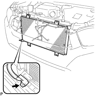
  1. Install the O-ring on the cooler refrigerant liquid pipe A.


    E153501
  1. Install the cooler refrigerant liquid pipe A on the cooler condenser assembly with the bolt.

    Torque:
    9.8 N*m{ 100 kgf*cm , 87 in.*lbf }


3. CONNECT DISCHARGE HOSE SUB-ASSEMBLY
  1. Remove the attached vinyl tape from the pipe and the connecting part of the cooler condenser assembly.

  1. Sufficiently apply compressor oil to a new O-ring and the fitting surface of the pipe joint.

    Compressor oil:
    ND-OIL 11 or equivalent

    NOTICE:
    1. Keep the O-rings and O-ring fitting surfaces clean from dirt or any foreign objects.
    2. Do not use any compressor oil other than ND-OIL 11 or equivalent. If any compressor oil other than ND-OIL 11 or equivalent is used, compressor motor insulation performance may decrease, resulting in a leakage of electric power.

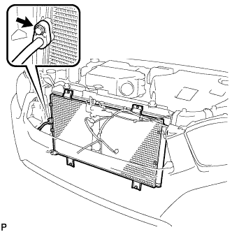
  1. Install the O-ring on the discharge hose sub-assembly.


    E153500
  1. Install the discharge hose sub-assembly on the cooler condenser assembly with the bolt.

    Torque:
    9.8 N*m{ 100 kgf*cm , 87 in.*lbf }


4. INSTALL RADIATOR ASSEMBLY


    A173817
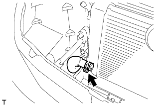
  1. Install the radiator assembly to the cooler condenser assembly with the 4 bolts.
    Torque:
    5.0 N*m{ 51 kgf*cm , 44 in.*lbf }


    A173816
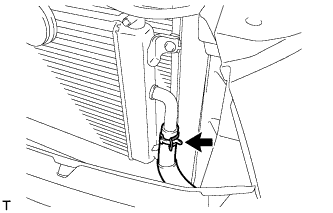
  1. Connect the water hose to the radiator assembly with the clamp.


    A173815
  1. Connect the water hose to the radiator assembly with the clamp.


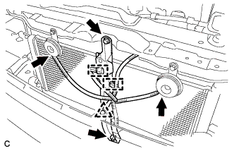
5. INSTALL HOOD LOCK SUPPORT SUB-ASSEMBLY


    A175943
  1. Install the hood lock support sub-assembly with the 2 bolts.

    Torque:
    7.0 N*m{ 71 kgf*cm , 62 in.*lbf }

  1. Install the clip and 2 clamps.

  1. Connect the 2 connectors.


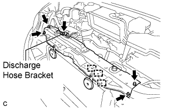
6. INSTALL UPPER RADIATOR SUPPORT SUB-ASSEMBLY


    A176030E01
  1. Install the upper radiator support sub-assembly with the 4 bolts.

    Torque:
    7.0 N*m{ 71 kgf*cm , 62 in.*lbf }

  1. Install the discharge hose bracket with the bolt.

    Torque:
    9.8 N*m{ 100 kgf*cm , 87 in.*lbf }

  1. Attach the 3 hood lock control cable clamps to the upper radiator support sub-assembly.


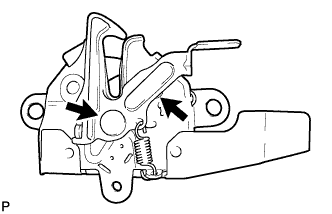
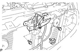
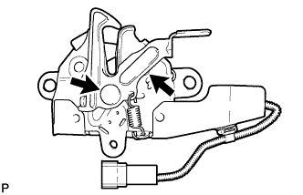
7. INSTALL HOOD LOCK ASSEMBLY (w/o Engine Hood Courtesy Switch)


    B174197
  1. Apply MP grease to the sliding areas of the lock.
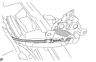


    B174190
  1. Connect the hood lock control cable.


    B174189
  1. Install the hood lock assembly with the 3 bolts.
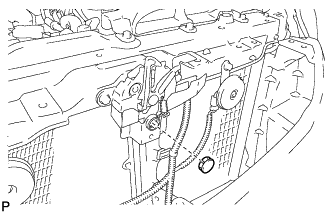
    Torque:
    8.0 N*m{ 82 kgf*cm , 71 in.*lbf }


    B174188
  1. Install the hood lock nut cap.


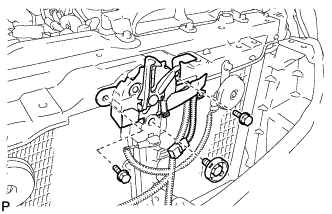
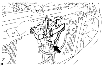
8. INSTALL HOOD LOCK ASSEMBLY (w/ Engine Hood Courtesy Switch)


    B174198
  1. Apply MP grease to the sliding areas of the lock.
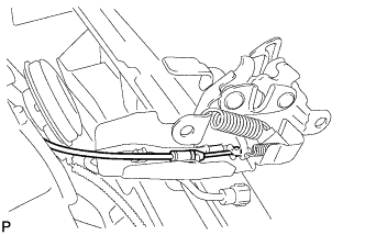


    B174194
  1. Connect the hood lock control cable.


    B174193
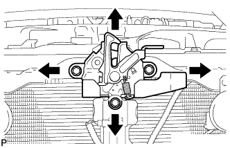
  1. Install the hood lock assembly with the 3 bolts.
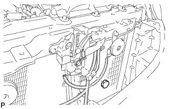
    Torque:
    8.0 N*m{ 82 kgf*cm , 71 in.*lbf }


    B174192
  1. Install the hood lock nut cap.


    B174191
  1. Connect the connector.


9. INSTALL AIR CLEANER CAP SUB-ASSEMBLY
  1. Install the air cleaner filter element to the air cleaner case sub-assembly.
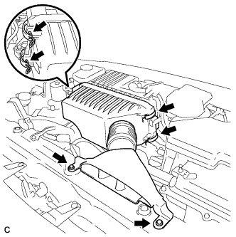


    A173489
  1. Install the air cleaner cap sub-assembly with the 4 clamps and 2 bolts.

    Torque:
    7.0 N*m{ 71 kgf*cm , 62 in.*lbf }


10. INSTALL RADIATOR GRILLE


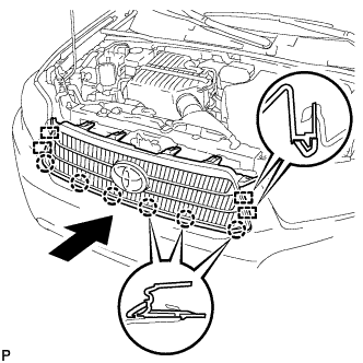
    B181114
  1. Engage the 4 guides and 6 claws, and install the radiator grille.
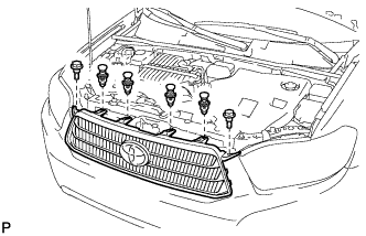


    B181109
  1. Install the 4 clips and 2 bolts.


11. INSPECT HOOD SUB-ASSEMBLY


  1. Check that the clearance measurements of areas A through D are within each standard range.
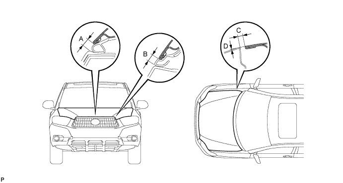

    B187090E01


    Standard clearance:

    Area
    Measurement
    Area
    Measurement
    A
    6.2 to 10.2 mm (0.244 to 0.402 in.)
    C
    2.5 to 5.5 mm (0.098 to 0.217 in.)
    B
    5.9 to 9.9 mm (0.232 to 0.390 in.)
    D
    -1.5 to 1.5 mm (-0.059 to 0.059 in.)


12. ADJUST HOOD SUB-ASSEMBLY


  1. Horizontally and vertically adjust the hood.
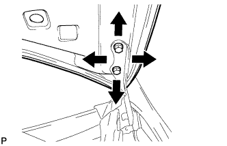


      B172912
    1. Loosen the 4 hinge bolts of the hood.

    2. Adjust the clearance between the hood and front fender by moving the hood.

    3. Tighten the 4 hinge bolts after the adjustment.

      Torque:
      13 N*m{ 133 kgf*cm , 10 ft.*lbf }


  1. Adjust the height of the front end of the hood using the cushion rubber.
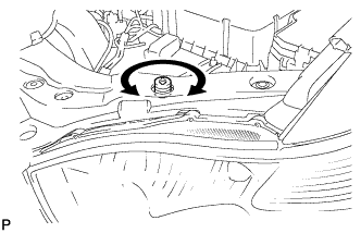


      B172913
    1. Adjust the cushion rubbers so that the heights of the hood and fender are aligned.

      HINT:
      Raise or lower the front end of the hood by turning the cushion rubber.


  1. Adjust the hood lock.


      B174192
    1. Remove the hood lock nut cap.


    2. B172915
    3. Loosen the 3 bolts.

    4. Tighten the bolts after the adjustment.

      Torque:
      8.0 N*m{ 82 kgf*cm , 71 in.*lbf }


    5. B174192
    6. Install the hood lock nut cap.

    7. Check that the striker can engage with the hood lock smoothly.


13. ADD COOLANT (for Inverter)

NOTICE:
  1. Do not reuse the drained coolant because it may contain foreign objects.
  2. If the vehicle is driven with air in the inverter cooling system, the following DTCs may be set.

    DTC Code
    Detection Item
    P0A01-725
    Motor Electronics Coolant Temperature Sensor Circuit Range / Performance
    P0A01-726
    Motor Electronics Coolant Temperature Sensor Circuit Range / Performance
    P0A78-284
    Drive Motor "A" Inverter Performance
    P0A7A-322
    Generator Inverter Performance
    P0A93-346
    Inverter Cooling System Performance
    P0A94-553
    DC / DC Converter Performance
    P0AEE-276
    Motor Inverter Temperature Sensor "A" Circuit Range / Performance
    P0AEE-277
    Motor Inverter Temperature Sensor "A" Circuit Range / Performance
    P3221-314
    Generator Inverter Temperature Sensor Circuit Range / Performance
    P3221-315
    Generator Inverter Temperature Sensor Circuit Range / Performance
    P3226-562
    DC/DC Boost Converter Temperature Sensor
    P3226-563
    DC/DC Boost Converter Temperature Sensor


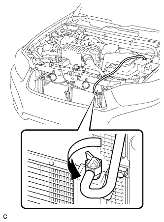
    A179308
  1. Loosen the bleeder plug shown in the illustration and connect a hose.

    NOTICE:
    Insert one end of the hose into the reserve tank.

  1. Add coolant to the reserve tank.


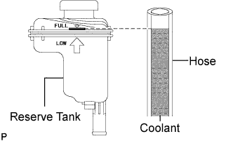
    C109303E01
  1. Add coolant until the level of coolant in the hose attached to the bleeder plug reaches the same level as the FULL line of the reserve tank.

    Coolant quantity:
    3.4 liter (3.6 US qts, 3.0 Imp. qts.)

  1. When using the Techstream:

    1. Connect the Techstream to the DLC3.

    2. Turn the power switch on (IG).

    3. On the Techstream, enter the following menus: Powertrain / Hybrid Control / Active Test / Activate the Water Pump.

    4. Keep the coolant at the FULL level in the reserve tank to compensate for the drop in coolant level when the air bleeds.

      Standard:
      Air bleeding from the coolant system is completed when the noise made by the water pump becomes smaller and the circulation of coolant in the reserve tank improves.

      HINT:
      Loud noise made by the water pump and poor circulation of coolant in the reserve tank indicates that there is air in the coolant system.

  1. When not using the Techstream:

    1. Turn the power switch on (READY). [*1]

    2. Turn the power switch off and add coolant to the FULL level because the coolant level drops as the air bleeds. [*2]

      NOTICE:
      1. Be sure to turn the power switch off before adding SLLC.
      2. Do not work on the components in the engine compartment while the vehicle is in the READY-on state because the engine is in intermittent operation.

    3. Repeat steps [*1] and [*2] until air bleeding from the coolant system is completed.

      Standard:
      Air bleeding from the coolant system is completed when the noise made by the water pump becomes smaller and the circulation of coolant in the reserve tank improves.

      HINT:
      Loud noise made by the water pump and poor circulation of coolant in the reserve tank indicates that there is air in the coolant system.

  1. When the air is completely bled from the coolant system, tighten the plug.
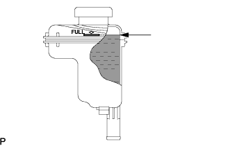


    C109304
  1. Add coolant to the FULL mark of the reserve tank.


14. CHARGE WITH REFRIGERANT
  1. Perform vacuum purging using a vacuum pump.


  1. Charge with refrigerant HFC-134a (R134a).
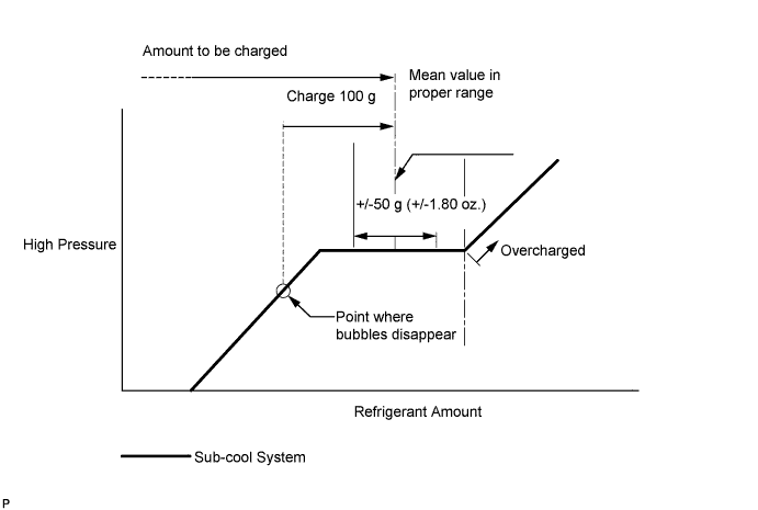

    E143108E02

    Standard (w/o Rear Air Conditioning System):
    550 to 650 g (19.4 to 22.9 oz.)

    Standard (w/ Rear Air Conditioning System):
    720 to 820 g (25.4 to 28.9 oz.)

    SST
    09985-20010   (09985-02130, 09985-02150, 09985-02090, 09985-02110, 09985-02010, 09985-02050, 09985-02060, 09985-02070, 09985-02080, 09985-02140)

    NOTICE:
    1. Do not turn the A/C on before charging with refrigerant. Doing so will cause the compressor to work without refrigerant, resulting in overheating of the cooler compressor.
    2. Approximately 100 g (3.53 oz.) of refrigerant may need to be charged after bubbles disappear. The refrigerant amount should be checked by quantity, not with the sight glass.
    3. Avoid using the gauge manifold set that had been used for vehicles with conventional compressor oil (ND-OIL11 or equivalent) as much as possible. This will cause compressor oil remaining in the manifold to enter the vehicle, resulting in insulation performance deterioration. A gauge manifold set that had been used 3 times or less can be reused if an appropriate one is not available.

    HINT:
    Ensure that sufficient refrigerant is available to recharge the system when using a refrigerant recovery unit. Refrigerant recovery units are not always able to recover 100% of the refrigerant from an A/C system.


15. INSPECT FOR COOLANT LEAK (for Inverter)
  1. Remove the reserve tank cap.

    CAUTION:
    To avoid the danger of being burned, do not remove the reserve tank cap while the coolant for the inverter is still hot.


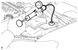
    A175857
  1. Install the radiator cap tester.

  1. Pump the radiator cap tester to 37 kPa (0.38 kgf/ cm2, 5.4 psi), and then check that the pressure does not drop.

    HINT:
    If the pressure drops, check the hoses, radiator, water pump, inverter with converter, and hybrid vehicle transaxle assembly for leakage.

  1. Reinstall the reserve tank cap.


16. WARM UP COMPRESSOR
  1. Keep the A/C switch on for at least 2 minutes to warm up the compressor.

    NOTICE:
    Be sure to warm up the compressor when turning the A/C on after removing and installing the cooler refrigerant lines (including the compressor), to prevent damage to the compressor.


17. INSPECT FOR REFRIGERANT LEAK
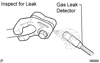
  1. After recharging with refrigerant gas, inspect for a refrigerant leak using a halogen leak detector.

  1. Carry out the test under the following conditions:
    1. Power switch off
    2. Secure good ventilation (the gas leak detector may react to volatile gases which are not refrigerant, such as evaporated gasoline and exhaust gas).
    3. Repeat the test 2 or 3 times.
    4. Make sure that there is some refrigerant remaining in the refrigeration system.
      When the compressor is off: approx. 392 to 588 kPa (4 to 6 kgf/cm2, 57 to 85 psi)


    I042222E25
  1. Using a gas leak detector, inspect for a leak from the refrigerant lines.


    N014519E06
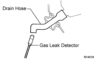
  1. Bring the gas leak detector close to the drain hose with the detector's power off, and then turn the detector on.

    HINT:
    1. After the blower motor has stopped, let the cooling unit stand for more than 15 minutes.
    2. Bring the gas leak detector sensor under the drain hose.
    3. When bringing the gas leak detector close to the drain hose, make sure that the gas leak detector does not react to volatile gases.
      If it is not possible to avoid interference from volatile gases, the vehicle should be lifted up to allow testing.

  1. If a gas leak is not detected from the drain hose, remove the blower motor control from the cooling unit. Insert the gas leak detector sensor into the unit and perform the test.

  1. Disconnect the pressure switch connector and leave it for approximately 20 minutes. Bring the gas leak detector close to the pressure switch and perform the test.


18. INSTALL COOL AIR INTAKE DUCT SEAL


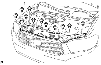
    B181107
  1. Install the cool air intake duct seal with the 11 clips.


19. INSTALL NO. 2 ENGINE ROOM SIDE COVER LH


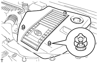
    A173813
  1. Fit the clips and install the No. 2 engine room side cover LH.

    NOTICE:
    1. Be sure to engage the clips securely.
    2. Do not apply excessive force or do not hit the cover to engage the clips. This may cause the cover to break.