 |
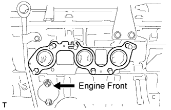
Install a new gasket as shown in the illustration.
EXHAUST MANIFOLD > INSTALLATION |
| 1. INSTALL NO. 2 EXHAUST MANIFOLD CONVERTER SUB-ASSEMBLY |
|
Install a new gasket as shown in the illustration.
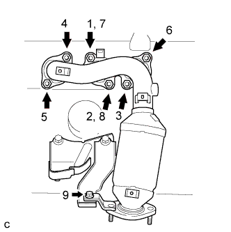 |
Install the No. 2 exhaust manifold converter sub-assembly with the 6 nuts and bolt. Using several steps, tighten the nuts and bolt uniformly in the sequence shown in the illustration.
| 2. INSTALL AIR FUEL RATIO SENSOR (for Bank 2) |
Temporarily tighten the air fuel ratio sensor to the exhaust manifold sub-assembly LH.
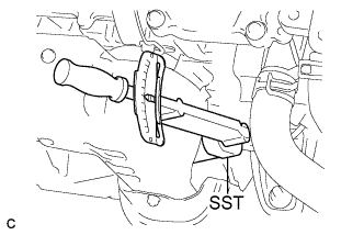 |
Using SST, fully tighten the air fuel ratio sensor to the exhaust manifold sub-assembly LH.
Connect the air fuel ratio sensor connector and clamp.
| 3. INSTALL FRONT EXHAUST PIPE ASSEMBLY |
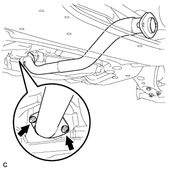 |
Install the front exhaust pipe assembly and a new gasket with 2 new nuts.
Connect the oxygen sensor connector.
| 4. INSTALL NO. 2 EXHAUST MANIFOLD HEAT INSULATOR |
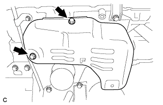 |
Install the front No. 2 exhaust manifold heat insulator with the 2 bolts.
| 5. INSTALL NO. 3 MANIFOLD CONVERTER INSULATOR |
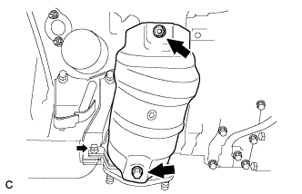 |
Install the front No. 3 manifold converter insulator with the bolt and nut.
| 6. INSTALL EXHAUST MANIFOLD SUB-ASSEMBLY RH |
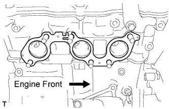 |
Install a new exhaust manifold gasket.
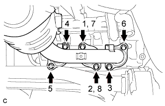 |
Install a new gasket and the exhaust manifold sub-assembly RH with the 6 nuts. Using several steps, tighten the nuts uniformly in the sequence shown in the illustration.
| 7. INSTALL MANIFOLD STAY |
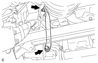 |
Install the manifold stay with the bolt and nut.
| 8. INSTALL NO. 1 EXHAUST MANIFOLD HEAT INSULATOR |
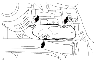 |
Install the No. 1 exhaust manifold heat insulator with the 3 bolts.
| 9. INSTALL AIR FUEL RATIO SENSOR (for Bank 1) |
Temporarily tighten the air fuel ratio sensor to the exhaust manifold sub-assembly RH.
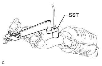 |
Using SST, fully tighten the air fuel ratio sensor to the exhaust manifold sub-assembly RH.
Connect the air fuel ratio sensor connector.
| 10. INSTALL FRONT NO. 3 EXHAUST PIPE SUB-ASSEMBLY |
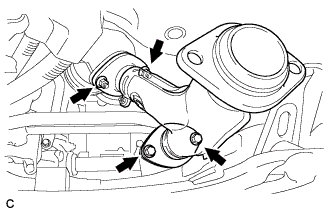 |
Install 2 new gaskets and the front No. 3 exhaust pipe sub-assembly with the 2 bolts and 2 new nuts.
Connect the oxygen sensor connector.
| 11. INSTALL CENTER EXHAUST PIPE ASSEMBLY |
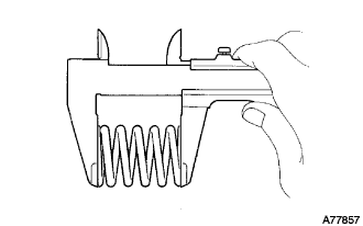 |
Using a vernier caliper, measure the free length of the compression spring.
| Minimum (front) | 41.5 mm (1.634 in.) |
| Minimum (rear) | 40.5 mm (1.594 in.) |
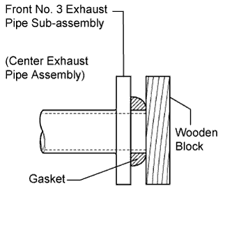 |
Using a plastic hammer and wooden block, tap in 2 new gaskets until their surfaces are flush with the front No. 3 exhaust pipe sub-assembly and center exhaust pipe assembly.
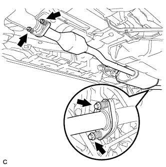 |
Connect the 3 exhaust pipe supports, and then install the center exhaust pipe assembly with the 4 compression springs and 4 bolts.
| 12. INSTALL NO. 2 ENGINE UNDER COVER |
Install the 2 bolts and No. 2 engine under cover.
| 13. INSTALL NO. 1 ENGINE UNDER COVER |
Install the 6 bolts, 2 screws, 2 clips and No. 1 engine under cover.
| 14. INSTALL AIR CLEANER CAP SUB-ASSEMBLY |
Install the air cleaner filter element to the air cleaner case sub-assembly.
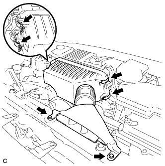 |
Install the air cleaner cap sub-assembly with the 4 clamps and 2 bolts.
| 15. INSTALL COOL AIR INTAKE DUCT SEAL |
Install the cool air intake duct seal with the 11 clips.
| 16. INSPECT FOR EXHAUST GAS LEAK |
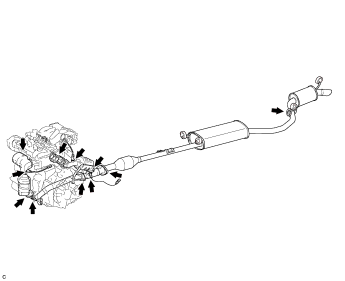
Check that there are no exhaust gas leaks from the points (joints of the exhaust pipes and installation points of each sensor) shown in the illustration.