 |
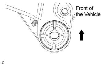
Temporarily install a new front suspension member body mounting rear cushion LH while confirming the installation direction.
- NOTICE:
- Position the front suspension member body mounting rear cushion in the correct direction.
FRONT SUSPENSION MEMBER > INSTALLATION |
| 1. INSTALL FRONT SUSPENSION MEMBER BODY MOUNTING REAR CUSHION LH |
|
Temporarily install a new front suspension member body mounting rear cushion LH while confirming the installation direction.
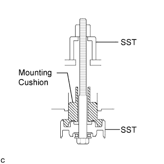 |
Install SST as shown in the illustration.
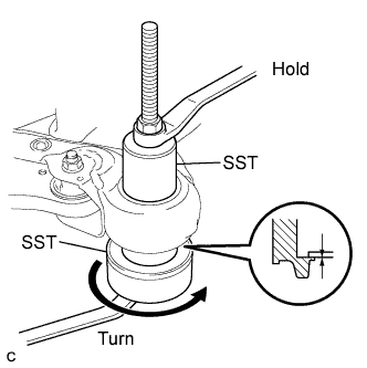 |
Using SST, install the front suspension member body mounting rear cushion LH as shown in the illustration.
| 2. INSTALL FRONT SUSPENSION MEMBER BODY MOUNTING REAR CUSHION RH |
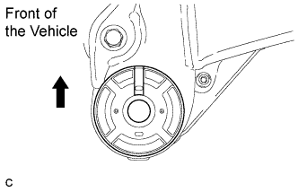 |
Temporarily install a new front suspension member body mounting rear cushion RH while confirming the installation direction.
Using SST, install the front suspension member body mounting rear cushion RH.
| 3. INSTALL FRONT SUSPENSION MEMBER BODY MOUNTING FRONT CUSHION |
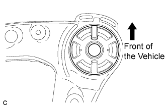 |
Temporarily install a new front suspension member body mounting front cushion while confirming the installation direction.
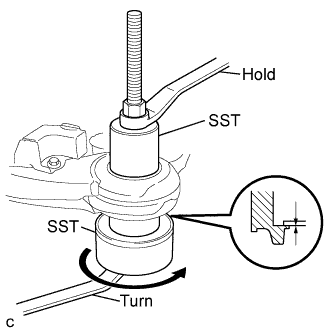 |
Using SST, install the front suspension member body mounting front cushion as shown in the illustration.
| 4. INSTALL FRONT SUSPENSION MEMBER BODY MOUNTING REAR STOPPER |
| 5. INSTALL FRONT SUSPENSION MEMBER BODY MOUNTING FRONT STOPPER |
| 6. INSTALL NO. 2 FRAME CROSSMEMBER DYNAMIC DAMPER |
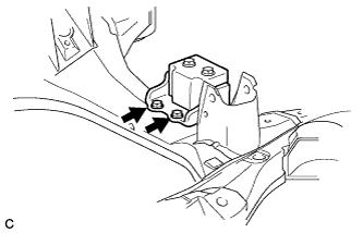 |
Install the No. 2 frame crossmember dynamic damper with the 2 bolts.
| 7. INSTALL FRONT SUSPENSION MEMBER DYNAMIC DAMPER |
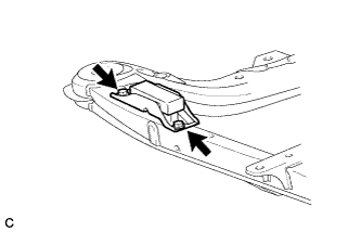 |
Install the front suspension member dynamic damper with the 2 bolts.
| 8. INSTALL FRONT LOWER SUSPENSION ARM LH |
Install the front lower arm bushing stopper to the front lower suspension arm.
Install the front lower suspension arm to the front frame assembly with the 3 bolts and nut, but do not tighten them yet.
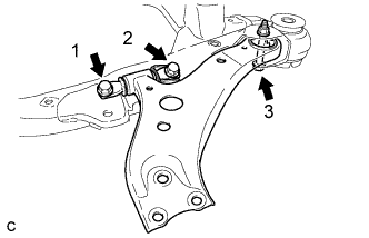 |
Tighten the 3 bolts in numerical order shown in the illustration.
| 9. INSTALL FRONT LOWER SUSPENSION ARM RH |
| 10. INSTALL REAR ENGINE MOUNTING INSULATOR |
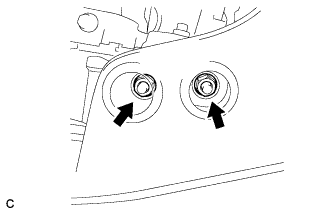 |
Install the rear engine mounting insulator with the 2 nuts.
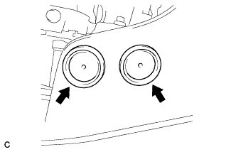 |
Install the 2 hole plugs.
| 11. INSTALL FRONT FRAME ASSEMBLY |
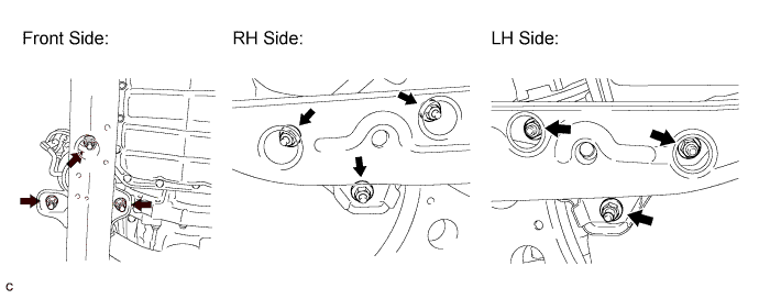
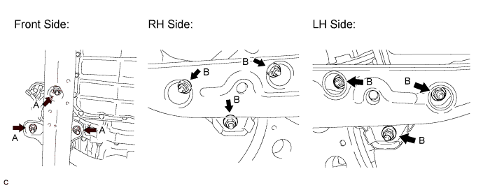
Temporarily install the engine assembly with transaxle with the 9 nuts.
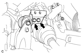 |
Connect the rear engine mounting insulator with the 2 bolts.
Fully tighten the 9 nuts.
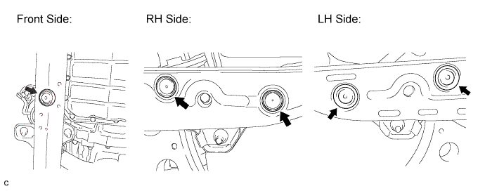
Install the 5 hole plugs.
| 12. INSTALL POWER STEERING LINK ASSEMBLY |
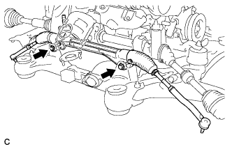 |
Install the power steering link assembly with the 2 bolts and 2 nuts.
| 13. INSTALL FRONT STABILIZER BAR WITH FRONT STABILIZER LINK ASSEMBLY |
| 14. INSTALL NO. 1 FRONT STABILIZER BRACKET LH |
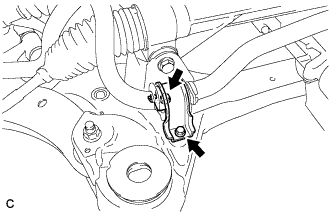 |
Install the No. 1 front stabilizer bracket LH to the front frame assembly with the 2 bolts.
| 15. INSTALL NO. 1 FRONT STABILIZER BRACKET RH |
| 16. INSTALL ENGINE ASSEMBLY WITH TRANSAXLE |
| 17. INSPECT AND ADJUST FRONT WHEEL ALIGNMENT |