 |
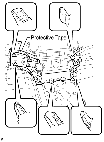
Apply protective tape to the areas shown in the illustration.
VOLTAGE INVERTER > REMOVAL |
| 1. REMOVE CENTER INSTRUMENT CLUSTER FINISH PANEL ASSEMBLY |
|
Apply protective tape to the areas shown in the illustration.
Using a moulding remover, disengage the 10 claws and 8 clips starting from the upper part of the center instrument cluster finish panel assembly.
Disconnect each connector and remove the center instrument cluster finish panel assembly.
| 2. REMOVE UPPER CONSOLE PANEL SUB-ASSEMBLY |
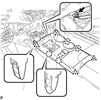 |
Disengage the 4 claws and 4 clips.
Disconnect the connector and remove the upper console panel sub-assembly.
| 3. REMOVE NO. 2 CONSOLE BOX DUCT (w/o Rear Air Conditioning System) |
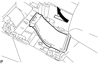 |
Remove the No. 2 console box duct as shown in the illustration.
| 4. REMOVE LOWER REAR CONSOLE BOX |
Remove the lower rear console box.
| 5. REMOVE CONSOLE BOX ASSEMBLY (w/o Rear Air Conditioning System) |
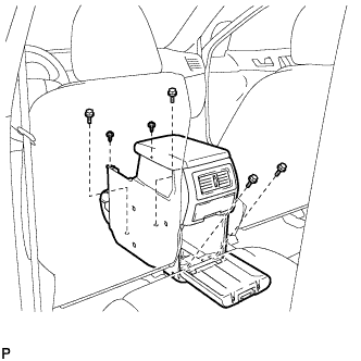 |
Remove the 4 bolts and 2 screws.
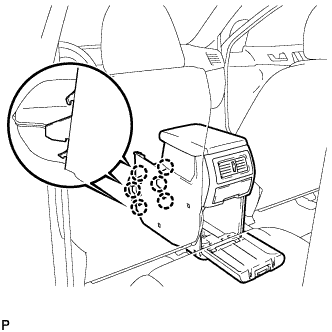 |
Disengage the 6 claws and remove the console box assembly.
| 6. REMOVE CONSOLE BOX ASSEMBLY (w/ Rear Air Conditioning System) |
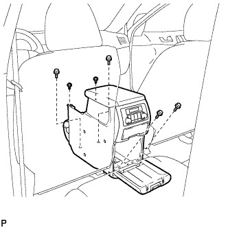 |
Remove the 4 bolts and 2 screws.
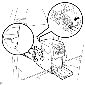 |
Disconnect the connector.
Disengage the 6 claws, and remove the console box assembly.
| 7. REMOVE FRONT NO. 1 CONSOLE BOX INSERT |
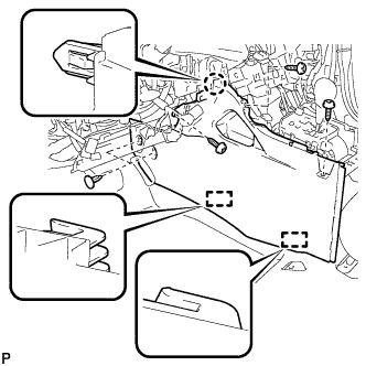 |
Using a clip remover, remove the 2 clips.
Remove the 3 screws <E>.
Disengage the claw and 2 guides, and then remove the front No. 1 console box insert.
| 8. REMOVE FRONT NO. 2 CONSOLE BOX INSERT |
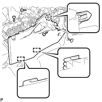 |
Using a clip remover, remove the clip.
Remove the 3 screws <E>.
Disengage the claw and 2 guides, and then remove the front No. 2 console box insert.
| 9. REMOVE VOLTAGE INVERTER ASSEMBLY |
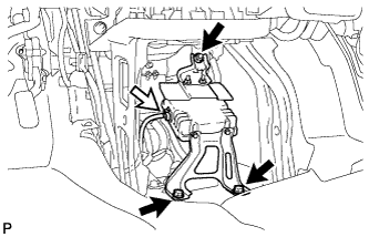 |
Disconnect the connector.
Remove the 2 bolts, nut and the voltage inverter assembly.