 |
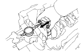
Using a dial indicator, measure the thrust clearance while moving the connecting rod back and forth.
- Standard thrust clearance:
- 0.15 to 0.30 mm (0.0059 to 0.0118 in.)
- Maximum thrust clearance:
- 0.35 mm (0.0138 in.)
CYLINDER BLOCK > INSPECTION |
| 1. INSPECT CONNECTING ROD THRUST CLEARANCE |
|
Using a dial indicator, measure the thrust clearance while moving the connecting rod back and forth.
| 2. INSPECT CONNECTING ROD OIL CLEARANCE |
Check that the matchmarks on the connecting rod and cap are aligned to ensure correct reassembly.
Remove the 2 connecting rod cap bolts.
Clean the crank pin, the bearing and the connecting rod.
Check the crank pin and bearing for pits and scratches.
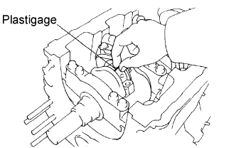 |
Lay a strip of Plastigage across the crank pin.
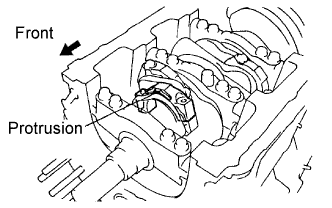 |
Check that the protrusion of the connecting rod cap is facing the correct direction.
Apply a light coat of engine oil to the threads of the connecting rod cap bolts.
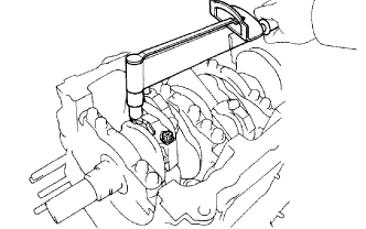 |
Tighten the bolts in several steps to the specified torque.
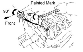 |
Mark the front side of each connecting cap bolt with paint.
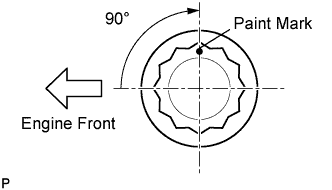 |
Retighten the cap bolts by 90° as shown in the illustration.
Remove the 2 bolts, the connecting rod cap and the lower bearing.
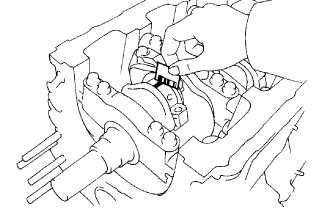 |
Measure the Plastigage at its widest point.
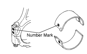 |
If replacing the bearing, replace it with one that has the same number as marked on the connecting rod.
| Mark | mm (in.) |
| "1" | 1.484 to 1.487 (0.0584 to 0.0585) |
| "2" | 1.488 to 1.490 (0.0586 to 0.0587) |
| "3" | 1.491 to 1.493 (0.0587 to 0.0588) |
| "4" | 1.494 to 1.496 (0.0588 to 0.0589) |
| 3. INSPECT CYLINDER BLOCK FOR WARPAGE |
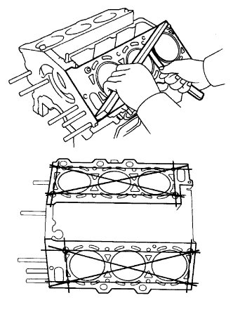 |
Using a precision straight edge and feeler gauge, measure the warpage of the contacting surface of the cylinder head gasket.
| 4. INSPECT CYLINDER BORE |
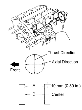 |
Using a cylinder gauge, measure the cylinder bore diameter at positions A and B in the thrust and axial directions.
| 5. INSPECT PISTON SUB-ASSEMBLY WITH PIN |
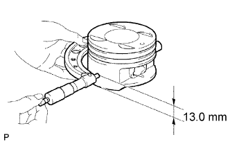 |
Using a micrometer, measure the diameter of the piston. When measuring the diameter, attach the micrometer to a location where 13.0 mm (0.512 in.) above from the piston bottom at the right angles to the piston pin hole.
| 6. INSPECT PISTON OIL CLEARANCE |
Subtract the piston diameter measurement from the cylinder bore diameter measurement.
| 7. INSPECT RING GROOVE CLEARANCE |
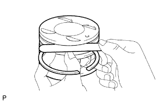 |
Using a feeler gauge, measure the clearance between a new piston ring and the wall of the ring groove.
| Item | Specified Condition |
| No. 1 | 0.03 to 0.08 mm (0.0012 to 0.0031 in.) |
| No. 2 | 0.02 to 0.06 mm (0.0008 to 0.0024 in.) |
| Oil (Side rail) | 0.03 to 0.11 mm (0.0012 to 0.0043 in.) |
| 8. INSPECT PISTON PIN OIL CLEARANCE |
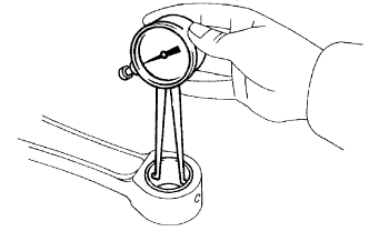 |
Using a caliper gauge, measure the inside diameter of the connecting rod bushing.
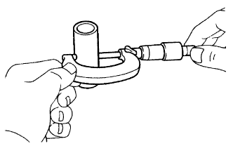 |
Using a micrometer, measure the piston pin diameter.
Subtract the piston pin diameter measurement from the bushing inside diameter measurement.
| 9. INSPECT PISTON RING END GAP |
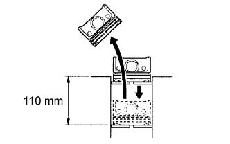 |
Using a piston, push the piston ring a little beyond the bottom of the ring travel, 110 mm (4.33 in.) from the top of the cylinder block.
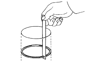 |
Using a feeler gauge, measure the end gap.
| Item | Specified Condition |
| No. 1 | 0.30 to 0.40 mm (0.0118 to 0.0157 in.) |
| No. 2 | 0.50 to 0.60 mm (0.0197 to 0.0236 in.) |
| Oil (Side rail) | 0.15 to 0.40 mm (0.0059 to 0.0157 in.) |
| Item | Specified Condition |
| No. 1 | 0.95 mm (0.0374 in.) |
| No. 2 | 1.05 mm (0.0413 in.) |
| Oil (Side rail) | 1.00 mm (0.0394 in.) |
| 10. INSPECT CRANKSHAFT THRUST CLEARANCE |
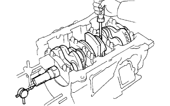 |
Using a dial indicator, measure the thrust clearance while prying the crankshaft back and forth with a screwdriver.
| 11. INSPECT CONNECTING ROD SUB-ASSEMBLY |
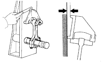 |
Using a rod aligner and feeler gauge, check the connecting rod alignment.
Check for misalignment.
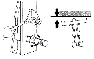 |
Check for twist.
| 12. INSPECT CONNECTING ROD BOLT |
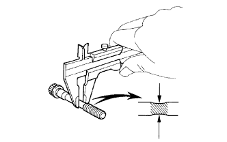 |
Using vernier calipers, measure the tension portion diameter of the bolt.
| 13. INSPECT CRANKSHAFT BEARING CAP SET BOLT |
|
Using vernier calipers, measure the tension portion diameter of the bolt.
| 14. INSPECT CRANKSHAFT |
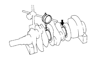 |
Using a dial indicator and V-blocks, measure the runout as shown in the illustration.
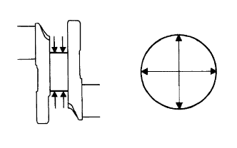 |
Using a micrometer, measure the diameter of each main journal.
Check each main journal for taper and out-of-round as shown.
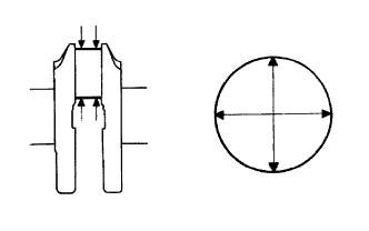 |
Using a micrometer, measure the diameter of each crank pin.
Check each crank pin for taper and out-of-round as shown.
| 15. INSPECT CRANKSHAFT OIL CLEARANCE |
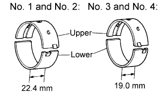 |
Clean each main journal and bearing.
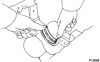 |
Align the bearing key with the keyway of the cylinder block, and push in the 4 upper bearings.
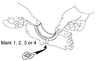 |
Align the bearing key with the keyway of the main bearing cap, and push in the 4 lower bearings.
Place the crankshaft on the cylinder block.
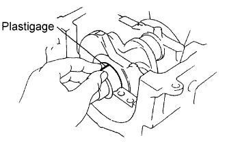 |
Lay a strip of Plastigage across each journal.
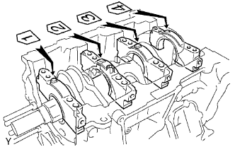 |
Examine the front marks and numbers and install the bearing caps on the cylinder block.
Apply a light coat of engine oil to the threads of the bearing cap bolts.
Temporarily install the 8 main bearing cap bolts to the inside positions.
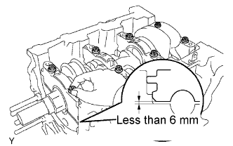 |
Install the main bearing cap by hand until clearance between the cylinder block and the bearing cap becomes 6 mm (0.23 in.) or less.
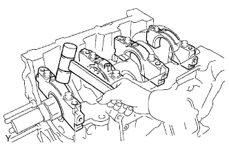 |
Using a plastic-faced hammer, lightly tap the bearing cap to ensure a proper fit.
Apply a light coat of engine oil to the threads of the main bearing cap bolts.
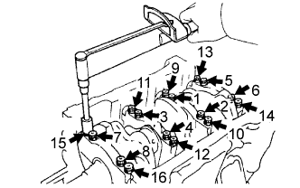 |
Using several steps, install and tighten the 16 main bearing cap bolts uniformly in the sequence shown in the illustration.
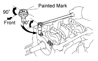 |
Mark the front side of the bearing cap bolts with paint.
Retighten the bearing cap bolts by 90° in the same sequence shown as step (l).
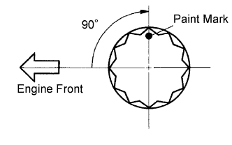 |
Check that each painted mark is now at a 90° angle to the front.
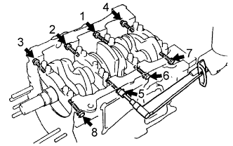 |
Using several steps, install and tighten the 8 main bearing cap bolts uniformly in the sequence shown in the illustration.
Remove the main bearing caps.
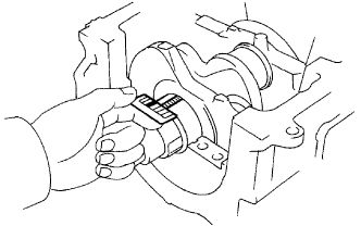 |
Measure the Plastigage at its widest point.
| Standard oil clearance | Maximum clearance | |
| No.1 and No.2 journals | 0.014 to 0.031 mm (0.0006 to 0.0012 in.) | 0.05 mm (0.0020 in.) |
| No.3 and No.4 journals | 0.026 to 0.043 mm (0.0010 to 0.0017 in.) | 0.06 mm (0.0024 in.) |
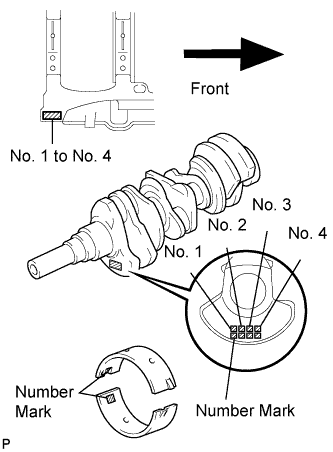 |
If replacing a bearing, replace it with one that has the same number. If the number of the bearing cannot be determined, select the correct bearing by adding together the numbers imprinted on the cylinder block and crankshaft, then refer to the table below for the appropriate bearing number. The No. 1 and No. 2 journal bearings come in sizes, marked "3", "4", "5", "6" and "7". The No. 3 and No. 4 journal bearings come in 5 standard bearing sizes, marked "1", "2", "3", "4" and "5".
| Crankshaft number mark | Cylinder block number mark | ||||||||||||||||
| 00 | 01 | 02 | 03 | 04 | 05 | 06 | 07 | 08 | 09 | 10 | 11 | 12 | 13 | 14 | 15 | 16 | |
| 00 | 3 | 3 | 3 | 3 | 4 | 4 | 4 | 4 | 4 | 4 | 4 | 5 | 5 | 5 | 5 | 5 | 5 |
| 01 | 3 | 3 | 4 | 4 | 4 | 4 | 4 | 4 | 4 | 4 | 5 | 5 | 5 | 5 | 5 | 5 | 5 |
| 02 | 3 | 4 | 4 | 4 | 4 | 4 | 4 | 4 | 5 | 5 | 5 | 5 | 5 | 5 | 5 | 5 | 6 |
| 03 | 4 | 4 | 4 | 4 | 4 | 4 | 4 | 5 | 5 | 5 | 5 | 5 | 5 | 5 | 5 | 6 | 6 |
| 04 | 4 | 4 | 4 | 4 | 4 | 4 | 5 | 5 | 5 | 5 | 5 | 5 | 5 | 6 | 6 | 6 | 6 |
| 05 | 4 | 4 | 4 | 4 | 4 | 5 | 5 | 5 | 5 | 5 | 5 | 5 | 6 | 6 | 6 | 6 | 6 |
| 06 | 4 | 4 | 4 | 4 | 5 | 5 | 5 | 5 | 5 | 5 | 5 | 6 | 6 | 6 | 6 | 6 | 6 |
| 07 | 4 | 4 | 5 | 5 | 5 | 5 | 5 | 5 | 5 | 5 | 6 | 6 | 6 | 6 | 6 | 6 | 6 |
| 08 | 4 | 5 | 5 | 5 | 5 | 5 | 5 | 5 | 6 | 6 | 6 | 6 | 6 | 6 | 6 | 6 | 7 |
| 09 | 5 | 5 | 5 | 5 | 5 | 5 | 5 | 6 | 6 | 6 | 6 | 6 | 6 | 6 | 6 | 7 | 7 |
| 10 | 5 | 5 | 5 | 5 | 5 | 5 | 6 | 6 | 6 | 6 | 6 | 6 | 6 | 7 | 7 | 7 | 7 |
| 11 | 5 | 5 | 5 | 5 | 5 | 6 | 6 | 6 | 6 | 6 | 6 | 6 | 7 | 7 | 7 | 7 | 7 |
| 12 | 5 | 5 | 5 | 5 | 6 | 6 | 6 | 6 | 6 | 6 | 6 | 7 | 7 | 7 | 7 | 7 | 7 |
| Crankshaft number mark | Cylinder block number mark | ||||||||||||||||
| 00 | 01 | 02 | 03 | 04 | 05 | 06 | 07 | 08 | 09 | 10 | 11 | 12 | 13 | 14 | 15 | 16 | |
| 00 | 1 | 1 | 1 | 1 | 2 | 2 | 2 | 2 | 2 | 2 | 2 | 3 | 3 | 3 | 3 | 3 | 3 |
| 01 | 1 | 1 | 2 | 2 | 2 | 2 | 2 | 2 | 2 | 2 | 3 | 3 | 3 | 3 | 3 | 3 | 3 |
| 02 | 1 | 2 | 2 | 2 | 2 | 2 | 2 | 2 | 3 | 3 | 3 | 3 | 3 | 3 | 3 | 3 | 4 |
| 03 | 2 | 2 | 2 | 2 | 2 | 2 | 2 | 3 | 3 | 3 | 3 | 3 | 3 | 3 | 3 | 4 | 4 |
| 04 | 2 | 2 | 2 | 2 | 2 | 2 | 3 | 3 | 3 | 3 | 3 | 3 | 3 | 4 | 4 | 4 | 4 |
| 05 | 2 | 2 | 2 | 2 | 2 | 3 | 3 | 3 | 3 | 3 | 3 | 3 | 4 | 4 | 4 | 4 | 4 |
| 06 | 2 | 2 | 2 | 2 | 3 | 3 | 3 | 3 | 3 | 3 | 3 | 4 | 4 | 4 | 4 | 4 | 4 |
| 07 | 2 | 2 | 3 | 3 | 3 | 3 | 3 | 3 | 3 | 3 | 4 | 4 | 4 | 4 | 4 | 4 | 4 |
| 08 | 2 | 3 | 3 | 3 | 3 | 3 | 3 | 3 | 4 | 4 | 4 | 4 | 4 | 4 | 4 | 4 | 5 |
| 09 | 3 | 3 | 3 | 3 | 3 | 3 | 3 | 4 | 4 | 4 | 4 | 4 | 4 | 4 | 4 | 5 | 5 |
| 10 | 3 | 3 | 3 | 3 | 3 | 3 | 4 | 4 | 4 | 4 | 4 | 4 | 4 | 5 | 5 | 5 | 5 |
| 11 | 3 | 3 | 3 | 3 | 3 | 4 | 4 | 4 | 4 | 4 | 4 | 4 | 5 | 5 | 5 | 5 | 5 |
| 12 | 3 | 3 | 3 | 3 | 4 | 4 | 4 | 4 | 4 | 4 | 4 | 5 | 5 | 5 | 5 | 5 | 5 |
| Item | Mark | mm (in.) |
| Cylinder block main journal bore diameter (A) | "00" "01" "02" "03" "04" "05" "06" "07" "08" "09" "10" "11" "12" "13" "14" "15" "16" | 66.000 (2.59842) 66.001 (2.59846) 66.002 (2.59850) 66.003 (2.59854) 66.004 (2.59858) 66.005 (2.59862) 66.006 (2.59866) 66.007 (2.59870) 66.008 (2.59874) 66.009 (2.59878) 66.010 (2.59881) 66.011 (2.59885) 66.012 (2.59889) 66.013 (2.59893) 66.014 (2.59897) 66.015 (2.59900) 66.016 (2.59905) |
| Crankshaft main journal diameter (B) | "00" "01" "02" "03" "04" "05" "06" "07" "08" "09" "10" "11" "12" | 61.000 (2.40157) 60.999 (2.40153) 60.998 (2.40149) 60.997 (2.40145) 60.996 (2.40141) 60.995 (2.40137) 60.994 (2.40133) 60.993 (2.40129) 60.992 (2.40126) 60.991 (2.40122) 60.990 (2.40118) 60.989 (2.40114) 60.988 (2.40110) |
| Standard bearing center wall thickness | "1" "2" "3" "4" "5" "6" "7" | 2.486 to 2.489 (0.09787 to 0.09799) 2.489 to 2.492 (0.09799 to 0.09811) 2.492 to 2.495 (0.09811 to 0.09823) 2.495 to 2.498 (0.09823 to 0.09835) 2.498 to 2.501 (0.09835 to 0.09846) 2.501 to 2.504 (0.09846 to 0.09858) 2.504 to 2.507 (0.09858 to 0.09870) |