 |
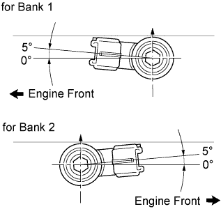
Install the 2 knock sensors so that it is horizontal as shown in the illustration. Then install the 2 bolts.
- Torque:
- 20 N*m{ 199 kgf*cm , 15 ft.*lbf }
- HINT:
- It is acceptable for the sensor to be tilted 5°.
ENGINE UNIT > INSTALLATION |
| 1. INSTALL KNOCK CONTROL SENSOR |
|
Install the 2 knock sensors so that it is horizontal as shown in the illustration. Then install the 2 bolts.
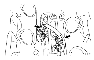 |
Connect the 2 knock sensor connectors.
| 2. INSTALL ENGINE OIL PRESSURE SWITCH ASSEMBLY |
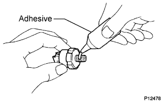 |
Apply adhesive to 2 or 3 threads of the oil pressure switch.
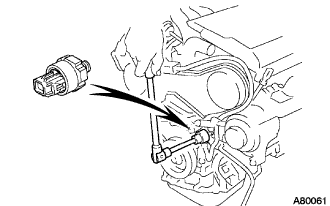 |
Using a 24 mm deep socket wrench, install the oil pressure switch.
| 3. INSTALL THERMOSTAT |
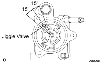 |
Install a new gasket to the thermostat.
Align the jiggle valve of the thermostat and water inlet, and insert the thermostat in the water inlet housing.
| 4. INSTALL INLET WATER |
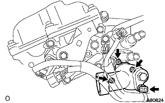 |
Install the water inlet with the 3 nuts.
Connect the wire harness clamp.
| 5. INSTALL INLET WATER PIPE |
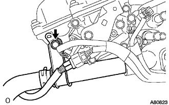 |
Install a new O-ring to the water inlet pipe.
Apply soapy water to the O-ring.
Connect the water inlet pipe to the water inlet.
Install the water inlet pipe to the cylinder head with the bolt.
| 6. INSTALL NO. 2 INTAKE AIR CONNECTOR BRACKET |
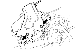 |
Install the No. 2 intake air connector bracket with the 2 bolts. Using several steps, tighten the bolts uniformly in the sequence shown in the illustration.
| 7. INSTALL NO. 1 COMPRESSOR MOUNTING BRACKET |
Temporarily install the No. 1 mounting bracket with the 4 bolts.
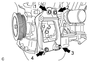 |
Install the mounting bracket by tightening the 4 bolts in the order shown in the illustration.
| 8. INSTALL ENGINE MOUNTING STAY BRACKET |
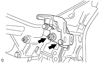 |
Install the engine mounting stay bracket with the bolt and nut.
| 9. INSTALL ENGINE MOUNTING BRACKET RH |
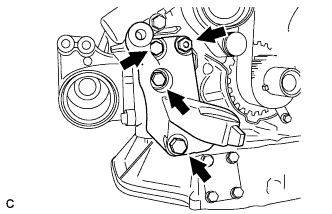 |
Install the 3 bolts and engine mounting bracket RH.
| 10. INSTALL NO. 2 MANIFOLD STAY |
Install the 2 bolts and No. 2 manifold stay.
| 11. INSTALL NO. 2 EXHAUST MANIFOLD CONVERTER |
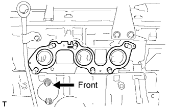 |
Install a new gasket as shown in the illustration.
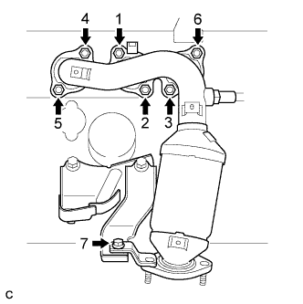 |
Install the No. 2 exhaust manifold converter with the 6 nuts and bolt. Using several steps, tighten the nuts uniformly in the sequence shown in the illustration.
Retighten nuts 1 and 2 shown in the illustration.
| 12. INSTALL NO. 2 EXHAUST MANIFOLD HEAT INSULATOR |
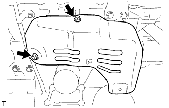 |
Install the No. 2 exhaust manifold heat insulator with the 2 bolts.
| 13. INSTALL NO. 3 MANIFOLD CONVERTER INSULATOR |
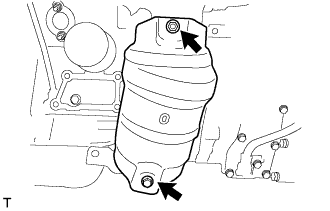 |
Install the No. 3 manifold converter insulator with the bolt and nut.
| 14. INSTALL IGNITION COIL ASSEMBLY |
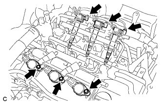 |
Install the 6 ignition coils with the 6 bolts.
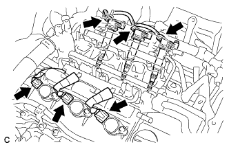 |
Connect the 6 ignition coil connectors.
| 15. INSTALL OUTLET WATER |
Install 2 new gaskets to the 2 cylinder heads.
Install the outlet water together with water by-pass hose No.1 and unlock the hose clamp.
Tighten the 2 bolts, 2 nuts and 2 washers.
Install the clamp.
Connect the engine coolant temperature sensor connector.
Connect the inlet radiator hose.
| 16. INSTALL INTAKE MANIFOLD |
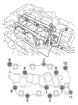 |
Install the intake manifold with the 9 bolts, 2 nuts and 2 washers. Using several steps, tighten the bolts and nuts uniformly in the sequence shown in the illustration.
Retighten the water outlet mounting bolts and nuts.
Install the ground cable with the nut.
Connect the heater inlet water hose.
| 17. INSTALL INTAKE AIR SURGE TANK |
Install a new gasket to the intake air surge tank.
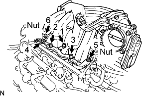 |
Using a socket hexagon wrench 8 mm, install the intake air surge tank with the 4 bolts and 2 nuts. Using several steps, tighten the bolts and nuts uniformly in the sequence shown in the illustration.
Connect the ground cable connector.
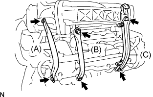 |
Install the No. 2 surge tank stay (A) with the 2 bolts.
Install the No. 1 surge tank stay (B) with the 2 bolts.
Install the No. 1 engine hunger (C) with the 2 bolts.
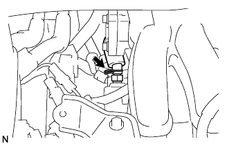 |
Connect the ventilation hose.
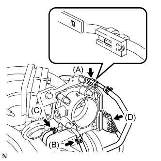 |
Connect the fuel vapor feed hose (A).
Connect the No. 3 water by-pass hose (B).
Connect the No. 2 water by-pass hose (C).
Connect the throttle motor connector (D).
| 18. INSTALL EMISSION CONTROL VALVE SET |
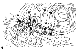 |
Install the emission control valve set with the 2 nuts (A).
Connect the No. 2 fuel vapor feed hose (B).
Connect the No. 1 fuel vapor feed hose (C).
Connect the wire harness clamp (D).
Connect the VSV connector (E).
| 19. INSTALL NO. 2 ENGINE HANGER |
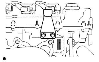 |
Install the No. 2 engine hanger with the 2 bolts in the correct direction shown in the illustration.
| No. 2 engine hanger | 12282-20020 |
| Bolt | 91641-80825 |
| 20. REMOVE ENGINE STAND |