 |
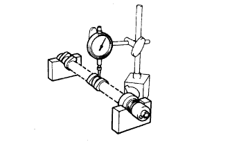
Inspect camshaft for runout.
Place the camshaft on V-blocks.
Using a dial indicator, measure the runout at the center journal.
- Maximum circle runout:
- 0.06 mm (0.0024 in.)
ENGINE UNIT > INSPECTION |
| 1. INSPECT CAMSHAFT |
|
Inspect camshaft for runout.
Place the camshaft on V-blocks.
Using a dial indicator, measure the runout at the center journal.
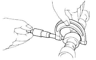 |
Inspect cam lobes.
Using a micrometer, measure the cam lobe height.
| Intake | Exhaust |
| 43.132 to 43.232 mm (1.6981 to 1.7020 in.) | 43.010 to 43.110 mm (1.6933 to 1.6972 in.) |
| Intake | Exhaust |
| 42.98 mm (1.6921 in.) | 42.86 mm (1.6874 in.) |
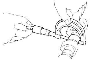 |
Inspect camshaft journals.
Using a micrometer, measure the journal diameter.
| 2. INSPECT CAMSHAFT TIMING GEAR ASSEMBLY |
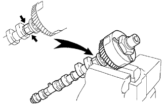 |
Clamp the camshaft in a vise on the hexagonal lobe.
Check that the VVT-i does not turn.
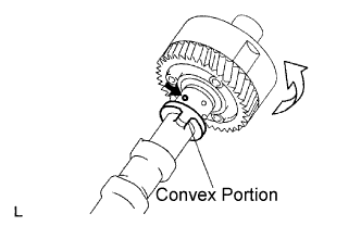 |
Cover all the oil ports with vinyl tape except the port on the advance angle side (nearest to the convex portion) shown in the illustration.
Apply about 100 kPa (1 kgf/cm2, 14 psi) of air pressure to the port on the advance angle side.
Turn the VVT-i to the advance angle side (the white arrow marked direction in the illustration) by hand.
Check that the VVT-i moves freely within about 30° range. Do not move the VVT-i unit to the most retard angle position as the lock-pin will be engaged again.
Turn the VVT-i by hand and lock it at the most retard angle position.
| 3. INSPECT CYLINDER HEAD SET BOLT |
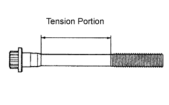 |
Using vernier calipers, measure the tension portion diameter of the bolt.
| 4. INSPECT TIMING BELT |
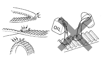 |
If there is premature parting:
If the belt teeth are cracked or damaged, check if either camshaft is locked.
If there is noticeable wear or cracks on the belt face, check if there are nicks on the side of the idler pulley lock and water pump.
If there is wear or damage to only one side of the belt, check the belt guide and the alignment of each pulley.
If there is noticeable wear on the belt teeth:
| 5. INSPECT CAMSHAFT GEAR BACKLASH |
Install the camshaft timing gear assembly.
Install the camshafts to the cylinder head.
Set the dial indicator to the teeth of the intake camshaft at a right angle (90°).
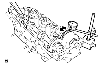 |
Measure the backlash of the camshaft timing gear at least 4 positions.
| 6. INSPECT CAMSHAFT THRUST CLEARANCE |
Install the camshafts.
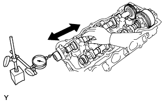 |
Using a dial indicator, measure the thrust clearance while moving the camshaft back and forth.
| 7. INSPECT CAMSHAFT OIL CLEARANCE |
Clean the bearing caps and camshaft journals.
Place the camshafts on the cylinder head.
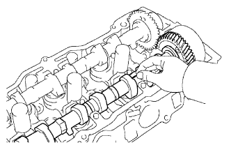 |
Lay a strip of Plastigage across each of the camshaft journal.
Install the bearing caps.
Remove the bearing caps.
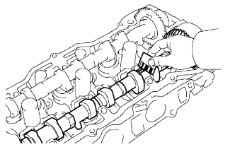 |
Measure the Plastigage at its widest point.
| Intake #4, #5 journals | Other journals |
| 0.025 to 0.057 mm (0.0010 to 0.0022 in.) | 0.025 to 0.062 mm (0.0010 to 0.0024 in.) |