 |
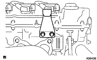
Remove the 2 bolts and No. 2 engine hanger.
ENGINE UNIT > REMOVAL |
| 1. INSTALL ENGINE STAND |
| 2. REMOVE NO. 2 ENGINE HANGER |
|
Remove the 2 bolts and No. 2 engine hanger.
| 3. REMOVE EMISSION CONTROL VALVE SET |
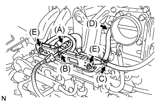 |
Disconnect the VSV connector (A).
Remove the wire harness clamp (B).
Disconnect the No. 1 fuel vapor feed hose (C).
Disconnect the No. 2 fuel vapor feed hose (D).
Remove the 2 nuts (E), then remove the emission control valve set.
| 4. REMOVE INTAKE AIR SURGE TANK |
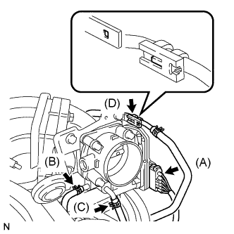 |
Disconnect the throttle motor connector (A).
Separate the No. 2 water by-pass hose (B).
Separate the No. 3 water by-pass hose (C).
Separate the fuel vapor feed hose (D).
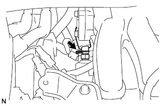 |
Disconnect the ventilation hose.
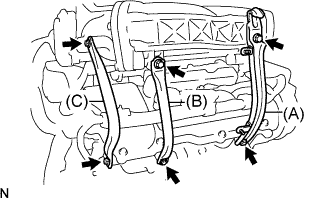 |
Remove the 2 bolts and No. 1 engine hanger (A).
Remove the 2 bolts and No. 1 surge tank stay (B).
Remove the 2 bolts and No. 2 surge tank stay (C).
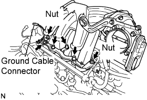 |
Disconnect the ground cable connector.
Using a socket hexagon wrench 8 mm, remove the 4 bolts.
Remove the 2 nuts, then remove the emission control valve bracket and the intake air surge tank.
Remove the gasket from the intake air surge tank.
| 5. REMOVE INTAKE MANIFOLD |
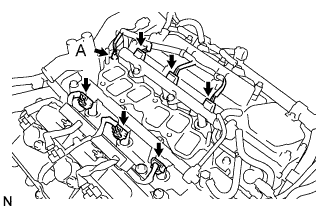 |
Remove the nut and disconnect the ground cable (A).
Disconnect the 6 fuel injector connectors.
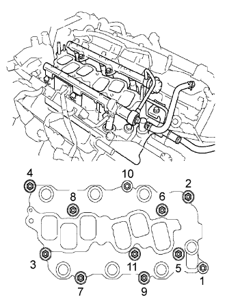 |
In order to remove the intake manifold, using several steps, remove the 9 bolts and 2 nuts in the sequence shown in the illustration.
| 6. REMOVE OUTLET WATER |
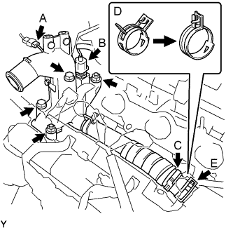 |
Disconnect the ground cable connector (A).
Disconnect the engine coolant temperature sensor connector (B).
Remove the clamp (C).
Remove the 2 bolts, 2 nuts and 2 washers.
Lock the hose clamp as shown in the illustration (D) and remove the water outlet together with No. 1 water by-pass hose (E).
Remove the 2 gaskets from the 2 cylinder heads.
| 7. REMOVE IGNITION COIL ASSEMBLY |
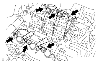 |
Disconnect the 6 ignition coil connectors.
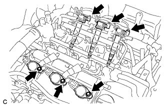 |
Remove the 6 bolts and 6 ignition coils.
| 8. REMOVE NO. 3 MANIFOLD CONVERTER INSULATOR |
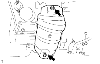 |
Remove the bolt, nut and No. 3 manifold converter insulator.
| 9. REMOVE NO. 2 EXHAUST MANIFOLD HEAT INSULATOR |
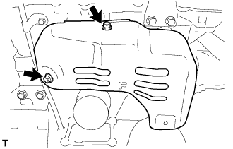 |
Remove the 2 bolts and No. 2 manifold heat insulator.
| 10. REMOVE NO. 2 EXHAUST MANIFOLD CONVERTER |
Disconnect the heated oxygen sensor connector.
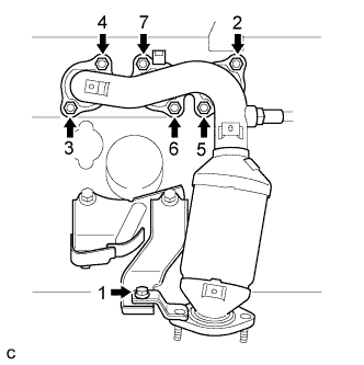 |
Using several steps, loosen and remove the 6 nuts and bolt in the sequence shown in the illustration.
Remove the No. 2 exhaust manifold converter and the gasket from the cylinder head LH.
| 11. REMOVE NO. 2 MANIFOLD STAY |
Remove the 2 bolts and No. 2 manifold stay.
| 12. REMOVE ENGINE MOUNTING BRACKET RH |
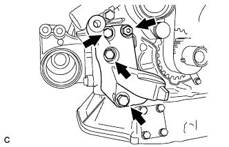 |
Remove the 3 bolts and engine mounting bracket RH.
| 13. REMOVE ENGINE MOUNTING STAY BRACKET |
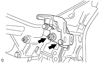 |
Remove the bolt, nut and engine mounting stay bracket.
| 14. REMOVE NO. 1 COMPRESSOR MOUNTING BRACKET |
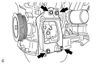 |
Remove the 4 bolts and No. 1 compressor mounting bracket.
| 15. REMOVE NO. 2 INTAKE AIR CONNECTOR BRACKET |
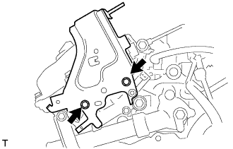 |
Remove the 2 bolts and No. 2 intake air connector bracket.
| 16. REMOVE INLET WATER PIPE |
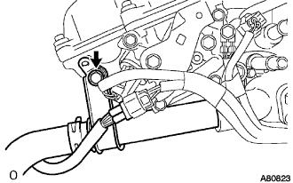 |
Remove the bolt and the water inlet pipe.
Remove the O-ring from the water inlet pipe.
| 17. REMOVE INLET WATER |
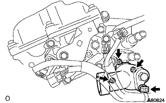 |
Disconnect the wire harness clamp.
Remove the 3 nuts and the water inlet.
| 18. REMOVE THERMOSTAT |
Remove the thermostat.
Remove the gasket from the thermostat.
| 19. REMOVE ENGINE OIL PRESSURE SWITCH ASSEMBLY |
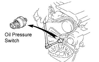 |
Using a 24 mm deep socket wrench, remove the oil pressure switch.
| 20. REMOVE KNOCK CONTROL SENSOR |
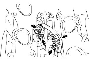 |
Disconnect the 2 knock sensor connectors.
Remove the 2 nuts, and then remove the 2 knock sensors.