 |
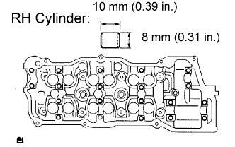
Using a plastic-faced hammer, tap in a new ring pin to the specified protrusion height.
- Protrusion height:
- 3 mm (0.12 in.)
CYLINDER HEAD > REASSEMBLY |
| 1. INSTALL RING PIN (for Bank 1) |
|
Using a plastic-faced hammer, tap in a new ring pin to the specified protrusion height.
| 2. INSTALL RING PIN (for Bank 2) |
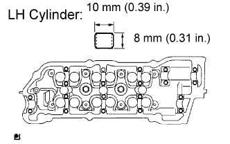 |
Using a plastic-faced hammer, tap in a new ring pin to the specified protrusion height.
| 3. INSTALL STUD BOLTS |
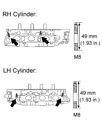 |
Install the stud bolts on the intake side.
Install the stud bolts on the exhaust side.
| 4. INSTALL VALVE SPRING SEAT |
Install the valve spring seat.
| 5. INSTALL VALVE STEM OIL SEAL OR RING |
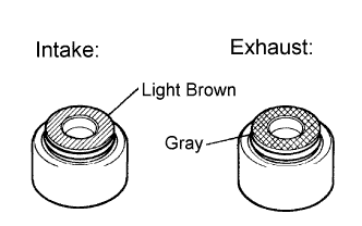 |
Apply a light coat of engine oil to the valve stem.
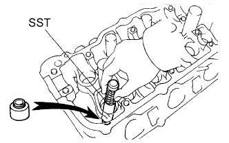 |
Using SST, push in new oil seals.
| 6. INSTALL INTAKE VALVE |
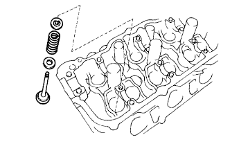 |
Install the valve, spring seat, valve spring, and spring retainer.
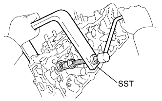 |
Using SST, compress the valve spring and place the 2 retainer locks around the valve stem.
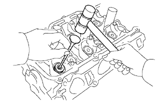 |
Using a plastic-faced hammer and a discarded valve (the tip is wrapped with tape), lightly tap the installed valve to fit into place.
| 7. INSTALL EXHAUST VALVE |
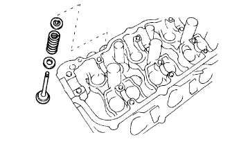 |
Install the valve, spring seat, valve spring, and spring retainer.
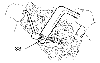 |
Using SST, compress the valve spring and place the 2 retainer locks around the valve stem.
|
Using a plastic hammer and a discarded valve (the tip is wrapped with tape), lightly tap the installed valve to fit into place.
| 8. INSTALL VALVE LIFTER |
Apply a light coat of engine oil to the valve lifter.
Install the valve lifter.
Check that the valve lifter rotates smoothly by hand.
| 9. INSTALL SEMICIRCULAR PLUG |
Remove any old seal packing (FIPG) material.
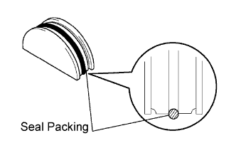 |
Apply seal packing to the semicircular plug grooves.
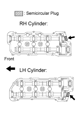 |
Install the 2 semi-circular plugs to the cylinder heads.
| 10. INSTALL NO. 2 STRAIGHT SCREW PLUG (for Bank 2) |
Using a 14 mm hexagon wrench, install 2 new gaskets and the 2 screw plugs.
| 11. INSTALL NO. 1 STRAIGHT SCREW PLUG (for Bank 1) |
Using a 14 mm hexagon wrench, install 2 new gaskets and the 2 screw plugs.