 |
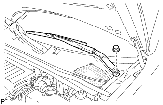
Remove the nut, and the front wiper arm and blade assembly LH.
VALVE CLEARANCE > ADJUSTMENT |
| 1. REMOVE FRONT WIPER ARM AND BLADE ASSEMBLY LH |
|
Remove the nut, and the front wiper arm and blade assembly LH.
| 2. REMOVE FRONT WIPER ARM AND BLEND ASSEMBLY RH |
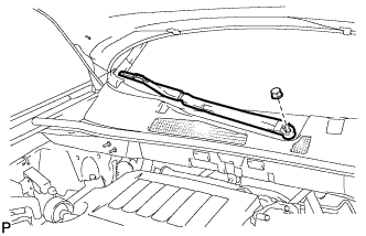 |
Remove the nut, and the front wiper arm and blade assembly RH.
| 3. REMOVE HOOD TO COWL TOP SEAL |
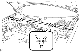 |
Disengage the 8 clips and remove the hood to cowl top seal.
| 4. REMOVE COWL TOP VENTILATOR LOUVER SUB-ASSEMBLY |
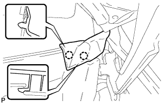 |
Disengage the 2 claws and disconnect the front fender to cowl side seal LH.
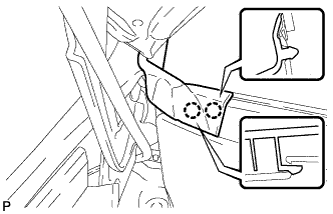 |
Disengage the 2 claws and disconnect the front fender to cowl side seal RH.
Remove the 2 clips.
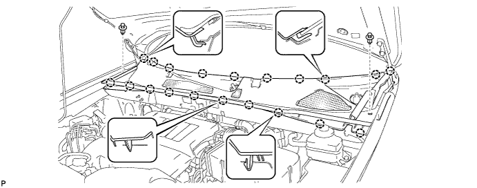
Disengage the 20 claws and remove the cowl top ventilator louver sub-assembly.
| 5. REMOVE WINDSHIELD WIPER MOTOR AND LINK ASSEMBLY |
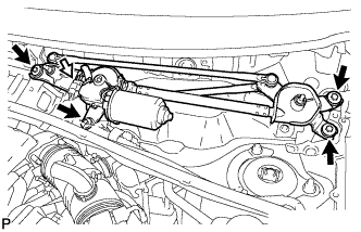 |
Disconnect the connector.
Remove the 4 bolts, and the windshield wiper motor and link assembly.
| 6. REMOVE OUTER COWL TOP PANEL SUB-ASSEMBLY |
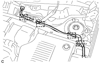 |
Disengage the 4 clamps and separate the wiper wire harness from the outer cowl top panel sub-assembly.
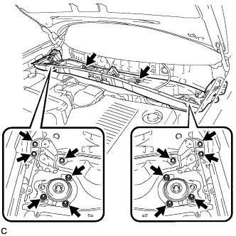 |
Remove the 8 bolts, 6 nuts, and the outer cowl top panel sub-assembly.
| 7. REMOVE NO. 2 ENGINE ROOM SIDE COVER LH |
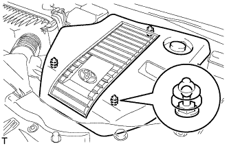 |
Remove the engine room side cover.
| 8. REMOVE FRONT WHEEL RH |
| 9. REMOVE NO. 1 ENGINE UNDER COVER |
Remove the 6 bolts, 2 screws, 2 clips and No. 1 engine under cover.
| 10. SEPARATE FRONT FENDER LINER RH |
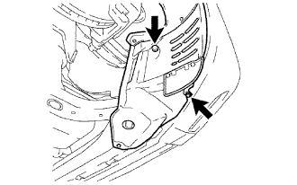 |
Remove the screw and clip, and separate the front fender liner.
| 11. REMOVE FRONT FENDER APRON SEAL RH |
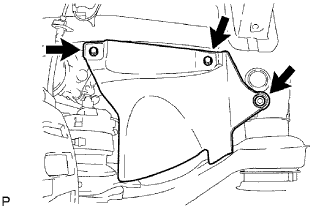 |
Remove the 2 bolts, clip and fender apron seal RH.
| 12. DRAIN COOLANT (for Engine) |
Loosen the radiator drain cock plug.
Loosen the cylinder block drain cock plugs.
Remove the radiator cap.
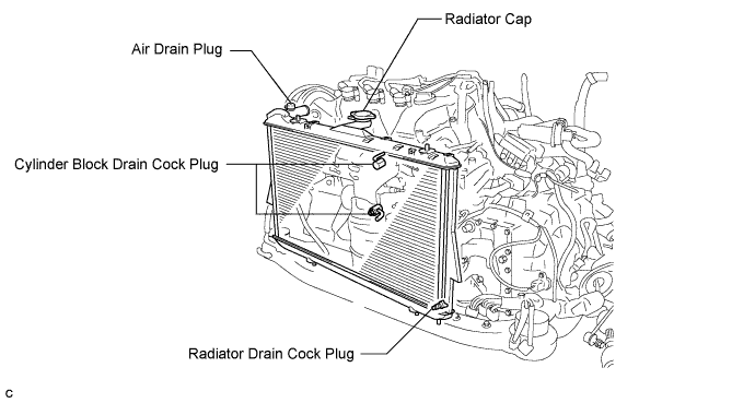
| 13. DRAIN ENGINE OIL |
Remove the oil filler cap.
Remove the oil drain plug and drain the oil into a container.
Clean and install the oil pan drain plug with a new gasket.
| 14. REMOVE AIR CLEANER CAP SUB-ASSEMBLY |
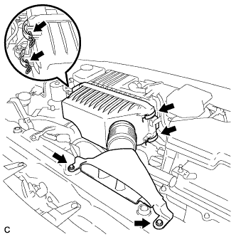 |
Remove the 2 bolts, 4 clamps and air cleaner cap sub-assembly.
Remove the air cleaner filter element from the air cleaner case.
| 15. REMOVE AIR CLEANER CASE SUB-ASSEMBLY |
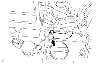 |
Separate the No. 1 ventilation hose.
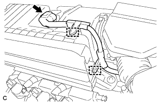 |
Disconnect the intake air flow meter connector.
Disconnect the 2 wire harness clamps from the air cleaner case sub-assembly.
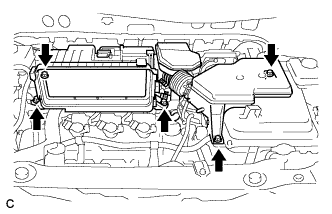 |
Remove the 5 bolts from the air cleaner case sub-assembly.
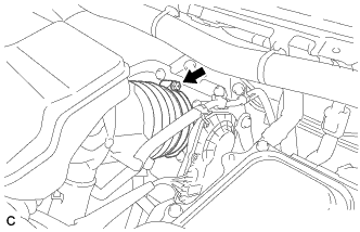 |
Loosen the hose clamp and separate the No. 1 air cleaner hose.
Remove the air cleaner case sub-assembly.
| 16. REMOVE EMISSION CONTROL VALVE SET |
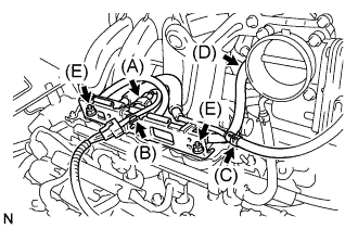 |
Disconnect the VSV connector (A).
Remove the wire harness clamp (B).
Disconnect the No. 1 fuel vapor feed hose (C).
Disconnect the No. 2 fuel vapor feed hose (D).
Remove the 2 nuts (E), then remove the emission control valve set.
| 17. REMOVE INTAKE AIR SURGE TANK |
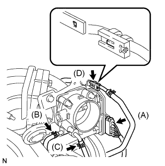 |
Disconnect the throttle motor connector (A).
Separate the No. 2 water by-pass hose (B).
Separate the No. 3 water by-pass hose (C).
Separate the fuel vapor feed hose (D).
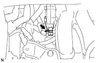 |
Disconnect the ventilation hose.
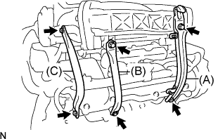 |
Remove the 2 bolts and No. 1 engine hanger (A).
Remove the 2 bolts and No. 1 surge tank stay (B).
Remove the 2 bolts and No. 2 surge tank stay (C).
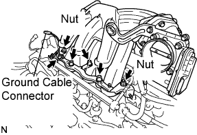 |
Disconnect the ground cable connector.
Using a socket hexagon wrench 8 mm, remove the 4 bolts.
Remove the 2 nuts, then remove the emission control valve bracket and the intake air surge tank.
Remove the gasket from the intake air surge tank.
| 18. DISCONNECT INLET RADIATOR HOSE |
| 19. REMOVE IGNITION COIL ASSEMBLY |
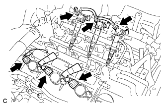 |
Disconnect the 6 ignition coil connectors.
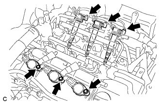 |
Remove the 6 bolts and 6 ignition coils.
| 20. REMOVE CYLINDER HEAD COVER SUB-ASSEMBLY |
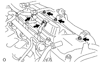 |
Remove the 2 engine wire harness clamps.
Remove the 3 nuts and disconnect the engine wire harness.
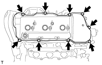 |
Remove the 9 bolts and the cylinder head cover.
| 21. REMOVE CYLINDER HEAD COVER SUB-ASSEMBLY LH |
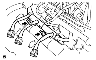 |
Using an E6 "TORX" socket wrench, remove the 2 bolts and disconnect the engine wire harness protector.
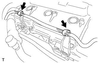 |
Remove the 2 engine wire harness clamps.
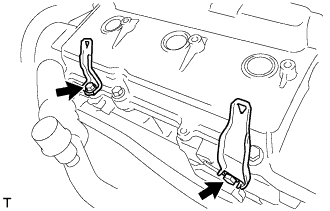 |
Remove the 2 bolts and 2 brackets.
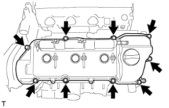 |
Remove the 9 bolts and the cylinder head cover.
| 22. INSPECT VALVE CLEARANCE |
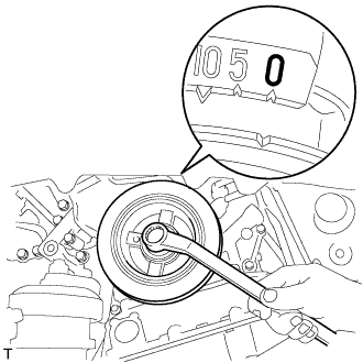 |
Turn the crankshaft pulley, and align the timing notch with the timing mark "0" of the No. 1 timing belt cover.
Check that the valve lifters on the No. 1 cylinder (IN and EX) are both loose.
If not, turn the crankshaft 1 revolution (360°) and align the mark as above.
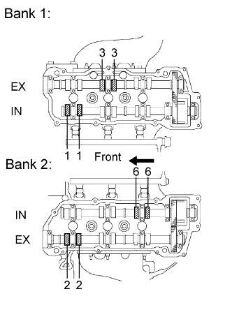 |
Check the valves indicated in the illustration.
Using a feeler gauge, measure the clearance between the valve lifter and the camshaft.
Record out-of-specification valve clearance measurements. They will be used later to determine the required replacement adjusting shim.
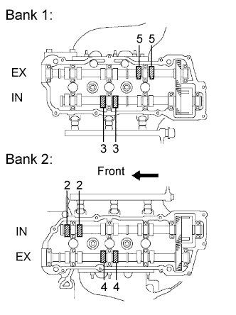 |
Turn the crankshaft 2/3 of a revolution (240°), and check the valves indicated in the illustration.
Using a feeler gauge, measure the clearance between the valve lifter and the camshaft.
Record out-of-specification valve clearance measurements. They will be used later to determine the required replacement adjusting shim.
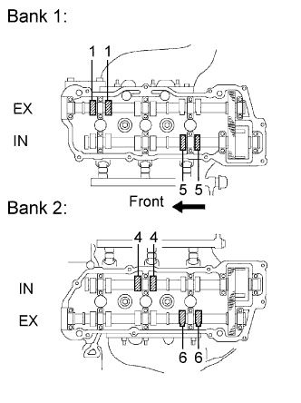 |
Turn the crankshaft 2/3 of a revolution (240°), and check the valves indicated in the illustration.
Using a feeler gauge, measure the clearance between the valve lifter and the camshaft.
Record out-of-specification valve clearance measurements. They will be used later to determine the required replacement adjusting shim.
| 23. ADJUST VALVE CLEARANCE |
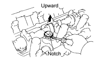 |
Turn the camshaft so that the cam lobe faces upward.
Turn the valve lifter with a screwdriver so that the notches are perpendicular to the camshaft.
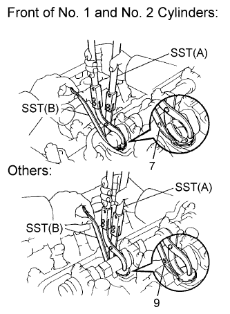 |
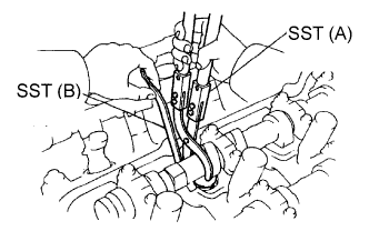
Using SST (A), press down the valve lifter and place SST (B) between the camshaft and valve lifter. Remove SST (A).
| SST (A) | 09248-05410 |
| SST (B) | 09248-05420 |
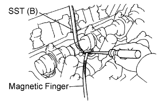 |
Using a screwdriver and magnetic pick-up tool, remove the adjusting shim.
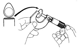 |
Using a micrometer, measure the thickness of the removed shim.
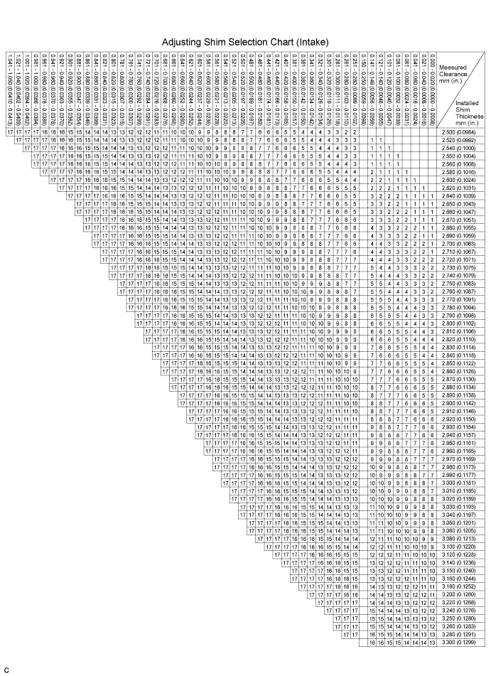
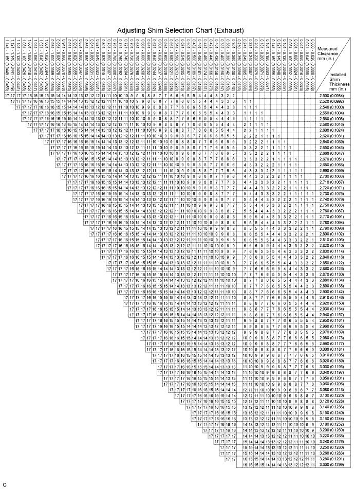
Calculate the thickness of a new shim so the valve clearance comes within the specified value.
| A | Thickness of new shim |
| B | Thickness of used shim |
| C | Measured valve clearance |
Select a new shim with a thickness as close as possible to the calculated values.
| EXAMPLE (Intake): Measured valve clearance = 0.45 mm (0.0177 in.) 0.45 mm (0.0177 in.) - 0.20 mm (0.0079 in.) = 0.25 mm (0.0098 in.) (Measured - Specification = Excess clearance) Used shim measurement = 2.80 mm (0.1102 in.) 0.25 mm (0.0098 in.) + 2.80 mm (0.1102 in.) = 3.05 mm (0.1201 in.) (Excess clearance + Used shim = Ideal new shim) Closest new shim = 3.05 mm (0.1201 in.) Select No. 12 shim |
| Shim No. | Thickness | Shim No. | Thickness |
| 1 | 2.500 (0.0984) | 10 | 2.950 (0.1161) |
| 2 | 2.550 (0.1004) | 11 | 3.000 (0.1181) |
| 3 | 2.600 (0.1024) | 12 | 3.050 (0.1201) |
| 4 | 2.650 (0.1043) | 13 | 3.100 (0.1220) |
| 5 | 2.700 (0.1063) | 14 | 3.150 (0.1240) |
| 6 | 2.750 (0.1083) | 15 | 3.200 (0.1260) |
| 7 | 2.800 (0.1102) | 16 | 3.250 (0.1280) |
| 8 | 2.850 (0.1122) | 17 | 3.300 (0.1299) |
| 9 | 2.900 (0.1142) |
| Shim No. | Thickness | Shim No. | Thickness |
| 1 | 2.500 (0.0984) | 10 | 2.950 (0.1161) |
| 2 | 2.550 (0.1004) | 11 | 3.000 (0.1181) |
| 3 | 2.600 (0.1024) | 12 | 3.050 (0.1201) |
| 4 | 2.650 (0.1043) | 13 | 3.100 (0.1220) |
| 5 | 2.700 (0.1063) | 14 | 3.150 (0.1240) |
| 6 | 2.750 (0.1083) | 15 | 3.200 (0.1260) |
| 7 | 2.800 (0.1102) | 16 | 3.250 (0.1280) |
| 8 | 2.850 (0.1122) | 17 | 3.300 (0.1299) |
| 9 | 2.900 (0.1142) |
 |
Place a new adjusting shim on the valve lifter with imprinted number facing down.
Press down the valve lifter with SST (A), and remove SST (B).
Recheck the valve clearance.
| 24. INSTALL CYLINDER HEAD COVER SUB-ASSEMBLY |
Install a new cylinder head cover gasket to the cylinder head cover sub-assembly.
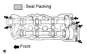 |
Apply seal packing to the cylinder head as shown in the illustration.
|
Install the cylinder head cover with the 9 bolts. Tighten the bolts uniformly in several steps.
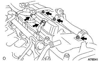 |
Install the engine wire harness with the 3 nuts and 2 clamps.
| 25. INSTALL CYLINDER HEAD COVER SUB-ASSEMBLY LH |
Install the a No. 2 cylinder head cover gasket to the cylinder head cover sub-assembly LH.
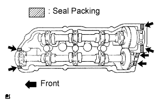 |
Apply seal packing to the cylinder head as shown in the illustration.
|
Install the cylinder head cover with the 9 bolts. Tighten the bolts uniformly in several steps.
|
Install the 2 brackets with the 2 bolts.
|
Install the 2 engine wire harness clamps.
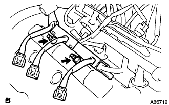 |
Using an E6 "TORX" socket wrench, install the engine wire harness protector with the 2 bolts.
| 26. INSTALL IGNITION COIL ASSEMBLY |
|
Install the 6 ignition coils with the 6 bolts.
|
Connect the 6 ignition coil connectors.
| 27. CONNECT INLET RADIATOR HOSE |
| 28. INSTALL INTAKE AIR SURGE TANK |
Install a new gasket to the intake air surge tank.
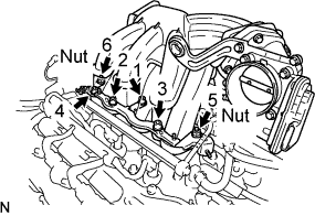 |
Using a socket hexagon wrench 8 mm, install the intake air surge tank with the 4 bolts and 2 nuts. Using several steps, tighten the bolts and nuts uniformly in the sequence shown in the illustration.
Connect the ground cable connector.
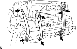 |
Install the No. 2 surge tank stay (A) with the 2 bolts.
Install the No. 1 surge tank stay (B) with the 2 bolts.
Install the No. 1 engine hunger (C) with the 2 bolts.
|
Connect the ventilation hose.
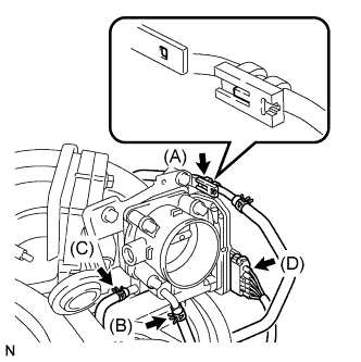 |
Connect the fuel vapor feed hose (A).
Connect the No. 3 water by-pass hose (B).
Connect the No. 2 water by-pass hose (C).
Connect the throttle motor connector (D).
| 29. INSTALL EMISSION CONTROL VALVE SET |
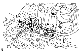 |
Install the emission control valve set with the 2 nuts (A).
Connect the No. 2 fuel vapor feed hose (B).
Connect the No. 1 fuel vapor feed hose (C).
Connect the wire harness clamp (D).
Connect the VSV connector (E).
| 30. INSTALL AIR CLEANER CASE SUB-ASSEMBLY |
|
Align the tab on the throttle body with the groove on the air cleaner hose and tighten the hose clamp.
|
Install the air cleaner case sub-assembly with the 5 bolts.
|
Connect the intake air flow meter connector.
Connect the 2 wire harness clamps to the air cleaner case.
|
Connect the No. 1 ventilation hose.
| 31. INSTALL AIR CLEANER CAP SUB-ASSEMBLY |
Install the air cleaner filter element to the air cleaner case.
|
Install the 2 bolts, 4 clamps and air cleaner cap sub-assembly.
| 32. ADD ENGINE OIL |
| 33. ADD COOLANT (for Engine) |
Tighten the radiator drain cock plug.
Tighten the cylinder block drain cock plugs.
Loosen the air drain plug.
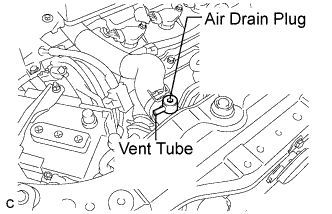 |
Install a vinyl tube to the vent tube located on the air drain plug.
Fill the radiator with engine coolant until the vinyl tube is filled with the coolant.
Tighten the air drain plug.
| Condition | Capacity |
| w/ rear heater | 12.8 liters (13.5 US qts, 11.2 lmp.qts) |
| w/o rear heater | 10.6 liters (11.2 US qts, 9.3 lmp.qts) |
Install the radiator cap securely.
Fill the radiator reservoir tank with coolant.
Warm up the engine until the thermostat opens. While the thermostat is open, allow the coolant to circulate for several minutes.
Stop the engine and wait until the coolant cools down.
Remove the radiator cap and check the coolant level inside the radiator.
If the coolant level is below the full level, perform the steps from (C) through (K) and repeat the operation until the coolant level stays at the full level.
Recheck the coolant level inside the radiator reservoir tank. If it is below the full level, add the coolant.
| 34. INSPECT FOR ENGINE COOLANT LEAK (for Engine) |
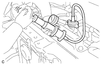 |
Fill the radiator with coolant and attach a radiator cap tester.
Pump the tester to 118 kPa (1.2 kgf/cm2, 17.1 psi), then check that the pressure does not drop.
If the pressure drops, check the hoses, radiator assembly and water pump assembly for leakage. If there are no signs or traces of external engine coolant leakage, check the heater core, cylinder block and cylinder head.
| 35. INSPECT FOR OIL LEAK |
| 36. INSTALL FRONT FENDER APRON SEAL RH |
|
Install the fender apron seal RH with the 2 bolts and clip.
| 37. INSTALL FRONT FENDER LINER RH |
|
Install the front fender liner with the screw and clip.
| 38. INSTALL NO. 1 ENGINE UNDER COVER |
Install the 6 bolts, 2 screws, 2 clips and No. 1 engine under cover.
| 39. INSTALL FRONT WHEEL RH |
| 40. INSTALL NO. 2 ENGINE ROOM SIDE COVER LH |
|
Fit the clips and install the No. 2 engine room side cover LH.
| 41. INSTALL OUTER COWL TOP PANEL SUB-ASSEMBLY |
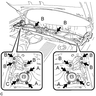 |
Install the outer cowl top panel sub-assembly with the 8 bolts and 6 nuts.
|
Engage the 4 clamps.
| 42. INSTALL WINDSHIELD WIPER MOTOR AND LINK ASSEMBLY |
|
Install the windshield wiper motor and link assembly with the 4 bolts.
Connect the connector.
| 43. INSTALL COWL TOP VENTILATOR LOUVER SUB-ASSEMBLY |
Engage the 20 claws.
Install the cowl top ventilator louver sub-assembly with the 2 clips.
|
Engage the 2 claws and connect the front fender to cowl side seal LH.
|
Engage the 2 claws and connect the front fender to cowl side seal RH.
| 44. INSTALL HOOD TO COWL TOP SEAL |
|
Engage the 8 clips and install the hood to cowl top seal.
| 45. INSTALL FRONT WIPER ARM AND BLADE ASSEMBLY RH |
Operate the wiper and stop the windshield wiper motor at the automatic stop position.
When reinstalling:
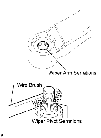 |
Clean the wiper arm serrations.
Clean the wiper pivot serrations with a wire brush.
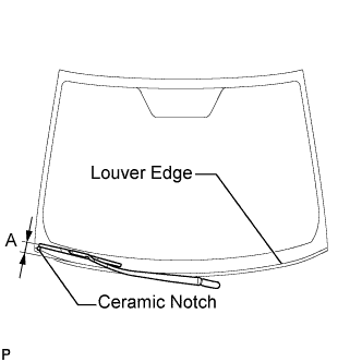 |
Install the front wiper arm and blade assembly RH with the nut to the position shown in the illustration.
| Area | Measurement |
| A | 25.6 mm (1.00 in.) |
| 46. INSTALL FRONT WIPER ARM AND BLADE ASSEMBLY LH |
Operate the wiper and stop the windshield wiper motor at the automatic stop position.
When reinstalling:
|
Clean the wiper arm serrations.
Clean the wiper pivot serrations with a wire brush.
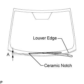 |
Install the front wiper arm and blade assembly LH with the nut to the position shown in the illustration.
| Area | Measurement |
| A | 31.9 mm (1.26 in.) |
Operate the front wipers while spraying washer fluid onto the windshield glass. Make sure that the front wipers function properly and the wipers do not come into contact with the vehicle body.