Home › Steering › POWER ASSIST SYSTEMS › POWER STEERING SYSTEM
RM3160E _55 Steering _019697 POWER ASSIST SYSTEMS _0104490 POWER STEERING SYSTEM J

POWER ASSIST SYSTEMS  POWER STEERING SYSTEM  TS and CG Terminal Circuit  


DESCRIPTION

Assist map writing can be performed after entering Signal Check by connecting the TS and CG terminals of the DLC3 using SST.

Click hereSteering>POWER ASSIST SYSTEMS>POWER STEERING SYSTEM>CALIBRATION

WIRING DIAGRAM
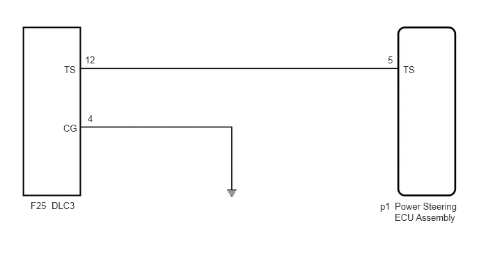
C269839E13
0.958,0.958 1.271,1.156 0.313,0.198 10 false TS 1.271,0.813 1.583,1.01 0.313,0.198 10 false 12 0.948,1.833 1.26,2.031 0.313,0.198 10 false CG 0.458,2.99 0.771,3.188 0.313,0.198 10 false F25 0.771,2.99 1.573,3.219 0.802,0.229 10 false DLC3 5.688,3 6,3.198 0.313,0.198 10 false p1 5.906,3 6.885,3.448 0.979,0.448 10 false Power Steering ECU Assembly 6.031,0.958 6.344,1.156 0.313,0.198 10 false TS 5.802,0.813 6.115,1.01 0.313,0.198 10 false 5 1.313,1.688 1.625,1.885 0.313,0.198 10 false 4

CAUTION / NOTICE / HINT

NOTICE:

If the power steering ECU assembly has been replaced, perform assist map writing.

Click hereSteering>POWER ASSIST SYSTEMS>POWER STEERING SYSTEM>CALIBRATION


PROCEDURE
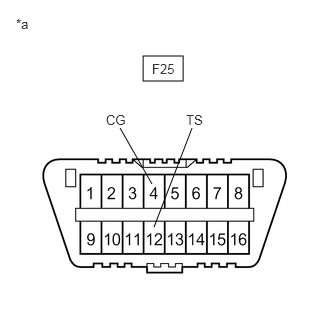
1.INSPECT DLC3
a.
C269872C23
1.49,0.583 1.906,0.844 0.417,0.26 1.583,1.917 1.25,1.333 false 1.604,2.365 2,1.333 false 0.167,0.167 0.479,0.365 0.313,0.198 10 false *a 1.583,0.635 1.896,0.833 0.313,0.198 10 false F25 1.104,1.167 1.417,1.417 0.313,0.25 10 false CG 1.938,1.167 2.25,1.417 0.313,0.25 10 false TS
*a Front view of DLC3


Turn the ignition switch to ON.


b.

Measure the voltage according to the value(s) in the table below.

Standard Voltage:
Tester Connection Condition Specified Condition
F25-12 (TS) - F25-4 (CG) Ignition switch ON 9 to 16 V


Result:
Proceed to
OK
NG


OK

REPLACE POWER STEERING ECU ASSEMBLY

NG

2.CHECK HARNESS AND CONNECTOR (POWER STEERING ECU ASSEMBLY - TS of DLC3)
a.

Disconnect the p1 power steering ECU assembly connector.


b.

Measure the resistance according to the value(s) in the table below.

Standard Resistance:
Tester Connection Condition Specified Condition
F25-12 (TS) - p1-5 (TS) Always Below 1 Ω
F25-12 (TS) or p1-5 (TS) - Body ground Always 10 kΩ or higher


Result:
Proceed to
OK
NG


OK

3.CHECK HARNESS AND CONNECTOR (CG of DLC3 - BODY GROUND)

NG

REPAIR OR REPLACE HARNESS OR CONNECTOR

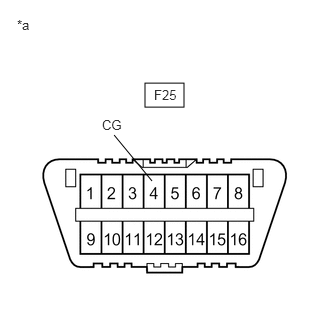
3.CHECK HARNESS AND CONNECTOR (CG of DLC3 - BODY GROUND)
a.
C207407C85
1.51,0.865 1.917,1.115 0.406,0.25 1.188,1.406 1.583,1.885 false 0.177,0.177 0.75,0.594 0.573,0.417 10 false *a 1.063,1.219 1.406,1.458 0.344,0.24 10 false CG 1.604,0.906 2.01,1.281 0.406,0.375 10 false F25
*a Front view of DLC3


Measure the resistance according to the value(s) in the table below.

Standard Resistance:
Tester Connection Condition Specified Condition
F25-4 (CG) - Body ground Always Below 1 Ω


HINT:

If troubleshooting has been carried out according to Problem Symptoms Table, refer back to the table and proceed to the next step before replacing the part.

Click hereSteering>POWER ASSIST SYSTEMS>POWER STEERING SYSTEM>PROBLEM SYMPTOMS TABLE


Result:
Proceed to
OK
NG


OK

REPLACE POWER STEERING ECU ASSEMBLY

NG

REPAIR OR REPLACE HARNESS OR CONNECTOR